-
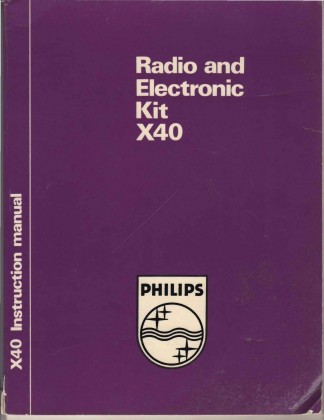
“Radio and Television” from the Macdonald Junior Reference Library
Posted on February 16th, 2025 No commentsAn old childhood book I found recently was “Radio and Television” from the Macdonald Junior Reference Library. Published in 1969, my copy was the 1972 reprint. It cost 45p new, but mine was bought for 20p in 1979 when it was withdrawn from stock at Rutland library.
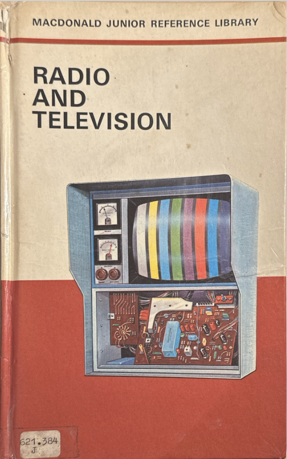
Front Cover of Radio and Television The illustrations are really nice. The text is mostly an encyclopedia style collection of terms related to radio and television technology. The terms are alphabetically sorted and seem to have been somewhat randomly chosen.
There is a big mistake on page 43 in the example of resistors in parallel. That was obvious to me when I looked through the book as an adult. I am surprised that the editors didn’t notice.
I remember even as a child I liked the look of the book, but was disappointed by the limits of the encyclopedia format.
-
Hantek6022BE USB Scope + OpenHantek6022 Fills a Useful Niche
Posted on December 29th, 2022 No commentsI’ve been looking for a scope that can be always on my bench for making quick assessments of circuits running at low frequencies. My electronics bench is also my work desk, so space is very much at a premium. My full-size analog and digital scopes are too big to leave set up there permanently (PS, a personal annoyance with modern digital scopes is that their shape means you can’t stack other equipment on top of them). I do have a little DSO Shell kit-scope which is OK, but a bit fiddly to operate and only has a single, very low frequency, channel.
There are of course various handheld scopes and scope-meters on the market, and maybe they would be a good option, but they need to be positioned in prime desk space to reach, and that would be awkward for me.
So far, my Sinclair/Thandar SC110A has been the best bet, but the small screen means it needs to be carefully adjusted to get a good view of a signal, and that’s not helpful when you are probing around a circuit.
I did look at other small analog scopes (I like analog for quick exploratory tests), but didn’t find anything that had a combination of price, size and capabilities that worked for me.
I started to wonder if I wasn’t better off going a different route and instead of looking for a small scope, I should make use of the PC and 4K monitor that’s always part of my workstation. I’ve resisted PC scopes on the assumption that the software will be grim, and the whole experience will be klunky. I’ve not had a good experience with test equipment integration with computers since using HP-IB and HP Basic to automate test systems back in the 1980s.
However, I was intrigued when I saw a cheap Hantek6022BE scope on eBay, and finding out that there is a well-liked, lightweight, and Open Source software platform for it. It was cheap enough that I was willing to give it a go and see whether this device could become my everyday scope.
When the unit came I was impressed. The box that needs to sit on the desk is fairly small, and can be easily tucked-away. It can even be stood in its side for a smaller footprint. Getting the open source drivers and OpenHantek6022 application installed was easy on Windows 10 using the instructions on the GitHub ReadMe. OpenHantek6022 has a level of maturity not often seen on niche open source applications. In particular, the documentation is very comprehensive.
In use I find the combination of hardware and software basic, but effective. OpenHantek6022 is very usable, though there are a few UI things I would tweak. Everything is visible and you don’t have the feeling of “menu diving” like you do on a lot of digital scopes. It’s also very responsive (due to a small memory depth I suppose) in a way that feels a lot like an analog scope.
I was also interested to see that the scope was compatible with Sikrok’s Pulseview software. I had some trouble getting the driver installed to work with Pulseview. The 6022 and similar devices have a slightly odd way of managing USB firmware (explained in this video) which can easily trip you up. I found Windows 10 was picking up the wrong driver once Pulseview was run. To get the right driver for Pulseview I had to:
- Start Pulseview with the 6022 connected
- Find the device in the Windows Device Manager
- Right-click and choose Update Driver
- Click “Browser My Computer”
- Click “Let Me Pick From A List of Available Drivers On My Computer”
- Then I was able to choose the driver from the install package. Ignore the warning about the driver not being optimal (or some such wording)
Pulseview ran fine, and might be a useful alternative to OpenHantek6022 if you want to do long captures, or to do protocol decoding on signals. One annoyance is that Pulseview doesn’t seem to allow you to configure x10 probes, so to get the right voltage scale you have to use the probes in the x1 setting. The wrong voltage on the display wouldn’t matter too much, except that having the wrong voltages then messes up the process of protocol decoding by stopping the conversion of analog captures to digital equivalents for further processing.
Overall I think this is a great package at the price. With the open source software it’s no fuss, and super-usable. Great for doing quick checks on circuits, and with the advantages of a big display I can even see myself using it for more demanding measurements.
EDIT TO ADD:
One potentially serious disadvantage of the 6022 is that the ground terminals are connected to the ground on your PC. If you connect the probe’s ground lead to something at a different voltage then there is a risk of damage to at least the USB port and potentially the whole PC.
For me, this is a risk I can live with, but it does depend on your use-cases, experience, and approach to risk whether this is an acceptable situation. It’s certainly something to consider.
-
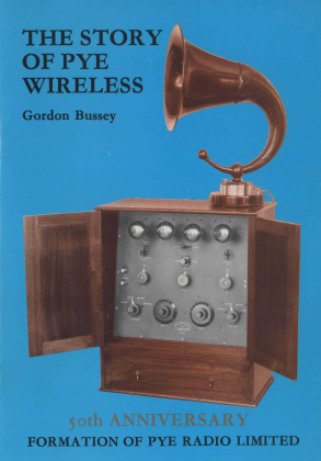
The Story of Pye Wireless
Posted on October 16th, 2018 No commentsBit of an odd one today – while helping my dad clear our some of my old books we found this pamphlet from 1986 – “The Story of Pye Wireless” by Gordon Bussey. I can’t find any other references to it on the web, and it seems well researched with some nice photos. So, to make it more widely available I’ve scanned it and made a copy available.
-
LushOne Synth – Briefcase Install
Posted on February 14th, 2017 No commentsJust a short video about the installation of my LushOne synth system in a briefcase to make a really neat, and unique, portable modular.
-
Fixing the cutest proper scope – Sincair/Thandar SC110A
Posted on July 31st, 2015 No commentsWhen doing some research on the web about my Philips X.40 electronics teaching kit I found out about the contemporary Philips EE2007 kit which had a battery operated CRT for the teenage nerd to play with. Just how cool is that? Even as an adult I immediately wanted something similar. The schematics of the EE2007 CRT module are easily available and I thought about building a clone using modern components but, to be honest, I am a bit of a scardy -cat when it comes to high voltages and I didn’t fancy getting to grips with the HT supply. Like so many others the project went on the back-burner.
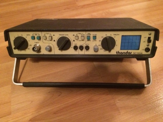
The original eBay photo – looks OK
Recently though I was thinking about upgrading my boat-anchor oscilloscope (it’s a 1980s(?) high-spec Hitachi hybrid analogue/sampling scope which is a joy to use but massive and very limited by today’s digital standards) and I thought I might be able to get a second hand modernish digital scope on eBay without spending too much. I didn’t find the ideal match there, but I did see a Thandar SC110A miniature analogue scope. It was love at first sight – a battery powered scope in a small, smart enclosure that matches my function generator which is always on my electronics bench. Some people find kittens cute but, for me, this dolls-house scope with its tiny 4cm diagonal screen just makes me feel all squeeeeeeeeeee. In XY mode I could use it like the EE2007 CRT but with added convenience of calibrated amplifiers and a timebase (no intensity input though).
The scope was described as working but I was always sceptical because eBayers are often economical with the truth and anyway not many people would know how to test it properly. Without being cheap it was at a price that I was prepared to spend for a bit of fun so I bought it expecting I would have to do some remedial work. When I got it there was good news and bad news. Good news was that you could get a “bright line” trace with no signal and most of the functions seemed to do vaguely the right thing. Bad news was that the display had awful distortion and freaky interactions between the X and Y axis. Also some of the input ranges on the Y axis didn’t seem to work. Time for fault-finding and recalibration using the handily supplied service manual.
To do the calibration you turn the scope upside down and take the bottom half of the case off which exposes the main circuit board and calibration controls. Once inside you see that the circuit board is actually branded Sinclair so you will understand if I was suspicious that it could ever be made to work properly at all. In fact Thandar and Sinclair seemed to have cooperated on several test instruments. Sinclair seems to have picked up the case mouldings from Thandar and Thandar sold several Sinclair instruments under their own brand (brave decision). This design seems to have originated in Sinclair and the CRT, as we will see, was custom made for Sinclair for their microvision pocket TVs.
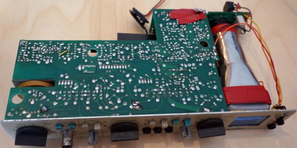
Ready for repair
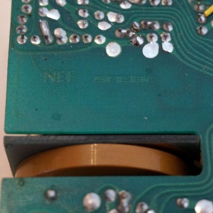
The mark of the devil
When I powered the scope up to calibrate it I realized that it had a fault that I had never seen before in any device. It worked, to an extent, the right way up but when you turned it upside down the trace disappeared and the whole thing seemed dead. I spent a long time turning the machine one way and then the other trying to find out where the thing stopped working and where the fault might me. Eventually I heard a little tinkle that seemed to come from inside the CRT which alerted me to the real cause. Sometimes electronic debugging involves all your senses. Removing the screening foils and looking inside the CRT I found that the glass supports holding one of the Y axis deflection plates and place had broken it the electrode was just flopping around – coming in to contact with other electrodes when the scope was turned upside down. Humm – eBay seller was dodgy on that one IMHO. Still, at least we have a plausible explanation for many of the problems.
Now, where do you get a custom made Sinclair CRT from in 2015? A few specialist shops had them listed at silly prices and were out of stock anyway. Then I had an inspiration – my searches had told me that the Sinclair Microvision TVs used the same tube so perhaps I could get one of those and cannibalize it. Back to eBay and, yes, there was a suitable Micovision for sale at not too high a price.
While waiting for the Microvision to arrive I did the best to fix the other problems working with the dodgy tube. To do this I had to strip the case off completely so I could run it the right way up and still access the controls. As a matter of routine I decided to replace all the polar capacitors (tants and electrolytics) in the design. It has a switching power supply which is nice and compact and gives it a very wide tolerance of supply voltages. In my experience switching power supplies were pretty rare at the time so this might have been a brave design. Normally in test equipment you see a lot of effort going in to conditioning the power supplies with great big capacitors to smooth them. In a sign of classic Sinclair cost-cutting the biggest supply capacitor in this scope is 47uF. It seems to work well enough though.
Next I turned my attention to the dead ranges on the Y Axis. . I spent a long time investigating possible faults with the switch or problems with the Y input buffer. In fact I should have checked the obvious. There is a “DC Offset” trim which needs to be set right to get the input buffer working correctly on all ranges. RTFM applies here.
After a few days my Microvision arrives in the post. I have to say it does look like a proper gadget and must have been quite a cool thing when it was new. As far as I can tell, with no suitable source for a modulated analogue TV signal available, it worked fine. Inside it’s in good condition and there is a surprising amount of space in the case. I feel a bit bad about whipping its tube out and swapping it for the broken one from the scope but I reckon it’s better to have one useful device that works than a TV that is no longer usable in the digital era.

My Sinclair Microvision
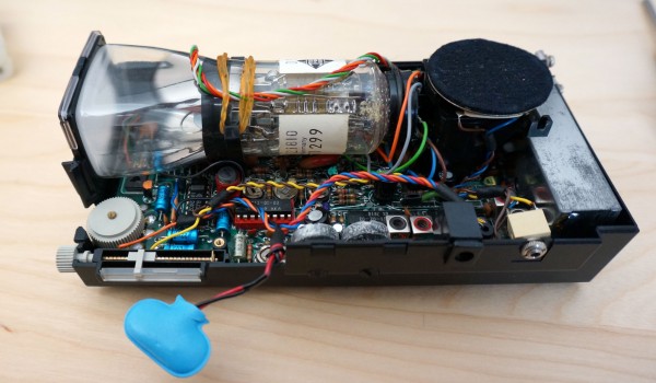
Interior of Sinclair Microvision with the precious tube
With the new tube in and the polar capacitors replaced the scope is working a lot better. Almost everything seems fine except that the Y signal is still very distorted. My fear at this stage is that the shorted electrode in the old tube has damaged some components in the Y amplifier and it’s going to need a lot of debugging and component sourcing to sort it out. In a moment of inspiration I wondered if looking at the lissajous figure from feeding the same signal to X and Y might be useful to understand what was going wrong. Instead of the expected straight line I saw a very definite knee – like some part of the amp was saturating. It turns out that setting up the calibration for the Y amplifier involves two interacting gain controls. The previous person to set this up had set one way too high and the other way too low forcing the amp in to saturation and clipping. Once both had been reset to near their midpoints the amp worked just fine. To be fair the service manual doesn’t explain how to set these controls very well and it requires a bit of electronics experience to know what you are supposed to do.
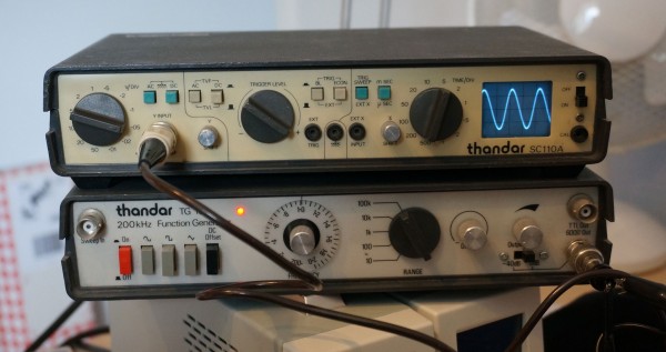
Aren’t they cute?!
With the Y amplifier recalibrated everything now works very nicely. Technically it’s certainly not a great scope but its simplicity is lovely. The tiny size is very practical. I like the immediacy of analogue scopes. You interact with them much more by intuition rather than digital scopes where you have to think. For answering the eternal electronic engineering question, “do I have a signal here?”, on my audio circuits it will be very handy. As I nice final touch I made a lead so I can use a USB battery booster that I got as a freebe from a trade-show as a power supply. It should run for about 10 hours on a charge. It’s just a really nice thing! I’ll maybe think about whether I can add an external control for the intensity and perhaps do a DIY TV on it.
Updates – 2022 – More History, Notes, Upgrades
I’ve been learning a few new things about this ‘scope recently which are worth saving, and also done some upgrades that I want to mention.
The SC110A CRT isn’t actually a Sinclair product – it was made by Telefunken and has model number D5-100W. In fact, the SC110A isn’t the only scope that used the CRT. Incredibly, a company in California called Non Linear Systems (NLS) made a two channel scope. Given how hard it is to properly see a single channel on that tiny CRT, it must be quite an experience to try and view two at once.
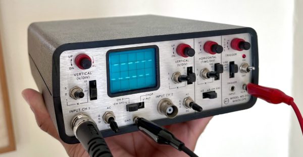
NLS MS-215 Scope – photo from Mohit Bhoite on Twitter An Upgrade for the SC110A (No Soldering Required)
The rotary knobs have a very small molding on one end to show what they are pointing to. These are almost invisible in use, and you can’t tell which end of the pointer you should be looking at. Put something very visible on the active end of the pointer to help read the dials.
Triggering
The trigger control on the SC110A is odd in that it uses different parts of the range for +ve and -ve triggering – normally this is done with a separate switch. On most scopes you would set the trigger control to the centre as a starting point to find the right trigger position. On the SC110A the middle position is actually the transition between +ve and -ve triggering and therefore not actually useful. The equivent to a normal “middle” position would be about 3 o’clock or 9 o’clock depending on whether you want +ve or -ve triggering. So, keep this in mind when trying to dial-in the trigger.
In fact the whole triggering system is rather hard to adjust and not very well scaled. At least on my scope a lot of the range of the trigger control is mostly useless. It looks like the circuit design can have a lot of variability in where the trigger lands, so to accommodate this they put a lot of “slop” in the trigger control.
I build a model of the trigger circuit in circuitjs to understand it better.
Based on the model and measurements on my scope, I’ve changed R4 from 10k to 13k in mine to try and make more of the trigger adjustment range useful.
Calibrated X Input
The manual for the SC110A says the X input is about 0.5V/division, but doesn’t give any calibration process for the input. I was doing some experiments with X-Y mode on the scope and wanted the X input to have a known scale. When I measured my scope the X input was more like 0.4V/dvision. It turns out that there are separate adjustments in the scope for the timebase speed and the X amplifier scale, so it is possible to adjust the X input to a precise value, it’s just that the calibration procedure doesn’t give a process.
I made my own adjustment by first adjusting the X amplifier gain so that the X input was on 0.5V/division, and then adjusting the timebase to run correctly using the process in the service manual.
-
Philips Radionics X40 Kit for Children
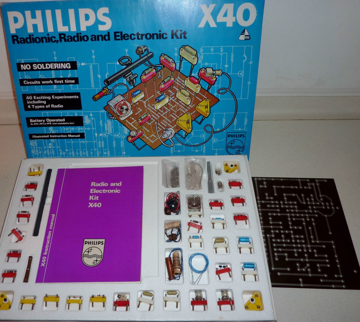
Posted on February 12th, 2015 No commentsMum and dad were always very generous to me, particularly when it came to toys that allowed me to explore my obsession with experimentation and construction. As quite young child I had got the “starter” Philips X20 electronics kit, which I played with a lot. Not too long afterwards, sometime in the late 1970s, and still as a pre-teen, I got the monster Philips Radionics X40 kit for my birthday.

Not my kit – my box is long-gone, but one from ebay in almost new condition.
For a child excited by technology (in a hands-on way, not the XBOX, iPad, App-store version of technology that many kids love today) the X40 was an impressive and exciting toy. It allowed you to build 40 projects – called “Experiments” in the manual – from testing to see whether water was conductive (boring) to regenerative radio receivers. The radios were the things I loved the best, particularly when dad and I had made special coils and we could tune it to get SW broadcasts. In the pre-Internet era hearing Voice of America and Radio Tirana was exciting.
As well as the radios the kit had some simple digital electronics. I learnt the function of all the basic logic gates from the X40. I also particularly remember a project which was a multivibrator driving a frequency divider. That project used all four transistors in the kit and seemed particularly sophisticated.
Dad put a lot of thought in to which system to buy and I think he liked the Radionics kit because it was open to expansion and the construction technique was very much like real electronics. The kit came with a large (A4 sized) PCB which was cleverly designed to work with all the projects. The components were mounted on plastic bases with brass screws that went through holes in the PCB to make the connections. Basically it was a solderless version of through-hole PCB construction and you got to see the real components pretty much unpackaged. When I went on to building projects on breadboard and veroboard it was an easy transition because I was so familiar with what things looked like from the X40.
I can’t claim that all the time I spent with the X40 taught me much about electronics theory. Even now I find the lumps of theory dished out in the manual rather hard to follow. At the time they were way over my head. What I did learn was a lot about practical electronics and also that electronics was an experimental science – you could just try changing stuff and seeing what worked. Also the presentation of the manual with the circuit diagrams and the physical layout side-by-side taught me to read circuit diagrams intuitively and that’s a skill that’s been really useful.
The connection with Philips seems to be a bit tenuous by the way. The X40 and other kits in the same range were rather confusingly co-branded “Philips” and “Radionics”. Philips had their own range of kits that was popular in Europe and as far as I can tell the X40 was a created by the UK Radionic company who I guess then applied the Philips brand under licence.
For the fundamentals of electronics using bipolar transistors I still think that the basic outline and structure of the X40 projects is very appropriate, so much so in fact that when I designed by Electronics for Absolute Beginners course I took the X40 as the initial starting point.
I still have the components and manual for my X40 kit – one day I’ll have to build some circuits to show you. In the meantime, here is a scan of my manual (48MB to it’s big!).
X40 Manual
I am not the only fan of the X40 on the web. Try these sites for more info, photos and manual scans:
- http://www.hansotten.com/index.php?page=x40
- http://ee.old.no/radionic/
- http://ee.old.no/library/ (Radionic scans near the bottom)
-
Kit building – Stylophone MIDI controller
Posted on May 18th, 2014 No commentsFor my birthday a few years ago, my girlfriend gave me one of the “new model” Stylophones. I proceeded to impress her with my technical prowess by failing to find the volume control (which was turned down to minimum) and pronouncing it dead on arrival. Once we found the volume control I demonstrated my musical prowess to the point where I was banned from using it further while she was in the house.
They are such a cute package that the urge to hack them is almost irresistible. The first problem though is how to get in – the two halves are joined with glued tabs and I am afraid that force is the only way. With luck you can keep the tabs intact enough to rejoin later.
Once inside the electronics consist of an amplifier joined to a main board with the inevitable custom IC hidden under black resin. Seemingly, there is not a vast amount of hacking potential then. Having pulled mine open it languished for a few months while I waited for inspiration for what to do next. When Jason Hotchkiss mentioned to me that he had a kit to turn the Stylophone in to a MIDI controller it grabbed my attention. More so when he warned me it was a difficult build and he had only sold a few because his warnings on how hard it was had dissuaded potential customers. Well, this sounded like a challenge to me.
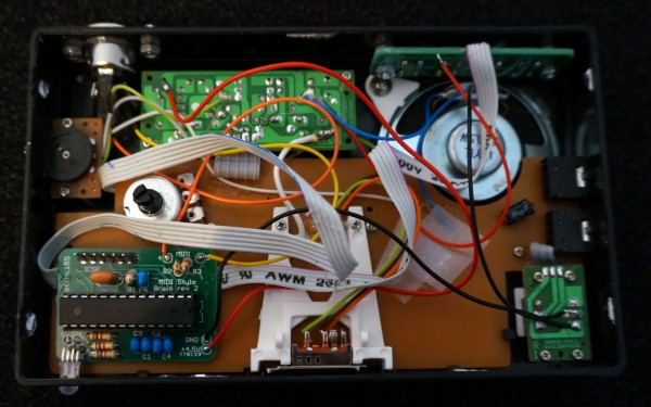
The kit comes with three different PCBs to add to the Stylophone and a large quantity of fine wire. For me it was an interesting build, certainly no harder to make than any of my video bending projects, but not a simple job either. As always Jason provides instructions that really help bring things together.
A few hours got everything installed and working first time. I rejoined the case with tape to allow me easy access in future in case I want to change anything else.
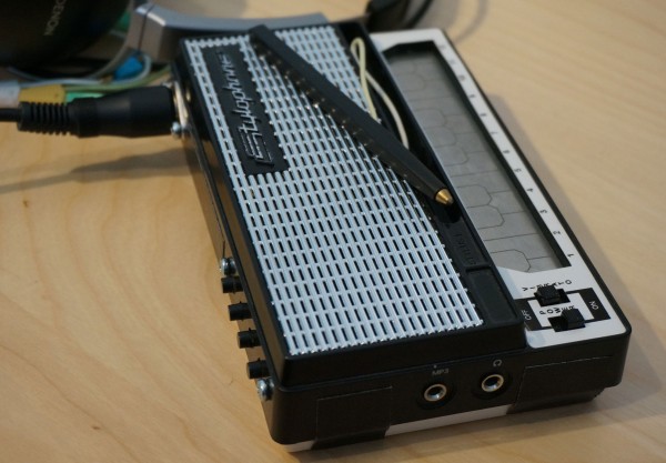
In use it is a really fun item. Playing a grand piano synth from a Stylophone is a rather crazy experience. You can whizz up and down the keyboard like a real virtuoso. An unexpected bonus (hey I don’t read the documentation) is that it contains a tilt sensor so you can do pitch-bend a modulation by turning the Stylophone. It’s a great controller when connected up to the LushOne.
-
Spectrum Analysis and GSM Broadcast Decoding in 2013
Posted on November 17th, 2013 No commentsThis post is about the low-cost SDR systems becoming available. I am afraid it’s not going to be very beginner friendly so I am going to assume that you have a general understanding of radio technology and SDR. In the last post I talked about the massive and expensive spectrum analyzers I used in the 1980s. In fact, even in that era I worked on SDR. Using a PDP 11 we analysed batch files of samples from radar systems to test new processing algorithms.
So why is SDR a hot topic now? Basically a combination of new hardware and the increasing power of desktop PCs has brought powerful SDR solutions within the reach of hobbyists and low budget researchers. There are two main strands:
Firstly, there is what we might call serious low-cost SDR. This consists of hardware boards in the spirit of something like the Arduino or Raspberries Pie which provide experimental but capable SDR platforms in a relatively low-cost package. Typically though these are not what you could call “cheap” as they still may cost hundreds or thousands of pounds. What you get is something with fairly good RF performance and perhaps the possibility of transmitting as well as receiving.
Secondly, there is what we might call seriously-low-cost SDR. This reuses very cheap USB TV receivers as SDR receivers. It is this ultra-low-cost SDR that I am going to talk about here.
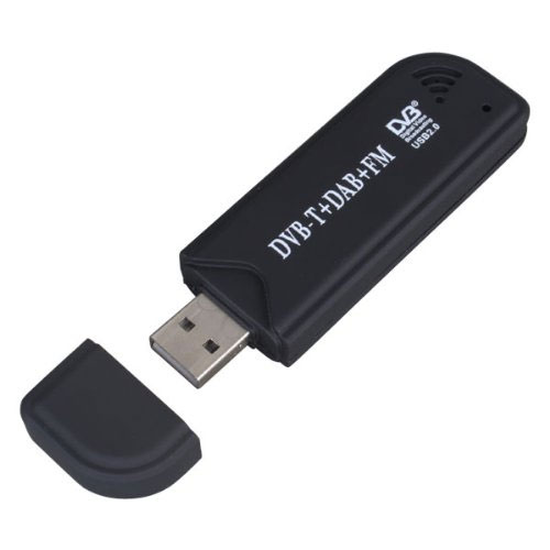
My SDR Hardware!
Two key points make ultra-low-cost SDR possible. Firstly it was discovered that certain chipsets widely used in USB TV receivers had a much wider tuning range than was needed for TV. The chipsets can also send the intermediate frequency I and Q samples directly over USB to the host computer. Secondly it was found that the processing power on normal PCs was sufficient to perform, in real time, SDR functions on the I and Q samples coming from the USB receiver.
I bought a dongle based on the RTL2832U+R820T chipset from Amazon for £12.50. This was a slight mistake as it was despatched from the Far East and took several weeks to arrive so my first advice would be to order locally. So what does a cheap USB TV receiver like this provide in terms of performance? According to this very useful stream of consciousness this chipset can tune from 24 – 1700 MHz. That covers FM, ham radio and GSM. It uses a 3.57 MHz intermediate frequency and has a tuning error of perhaps 30 ppm which is relatively stable for a particular dongle when it is warm.
The intermediate frequency sampling is 8-bit and around 2MS/s is an achievable sampling rate. The dynamic range is about 45 dB. My experience is that the biggest problem is various spurious signals appearing that seem to by primarily due to interference at the intermediate frequency. There are various homebrew solutions to improve screening described on the web but I haven’t tried these.
My 1st experiment was using SDR# running on Windows. This was easy to install using a recipe I found on the web. I just hooked up a few meters of wire to use as an antenna. I was easily able to scan the FM and air bands to receive various stations. Once the “Correct IQ” option was checked I was able to receive sounds. I also looked around 900 MHz and saw what I thought were probably GSM cells. It’s not really fair to compare my 2013 technology to the spectrum analyzers of 1986, but as a way of visualising common radio signals it serves the same purpose for 0.07% of the cost (less allowing for inflation)! On its own I find this fascinating.
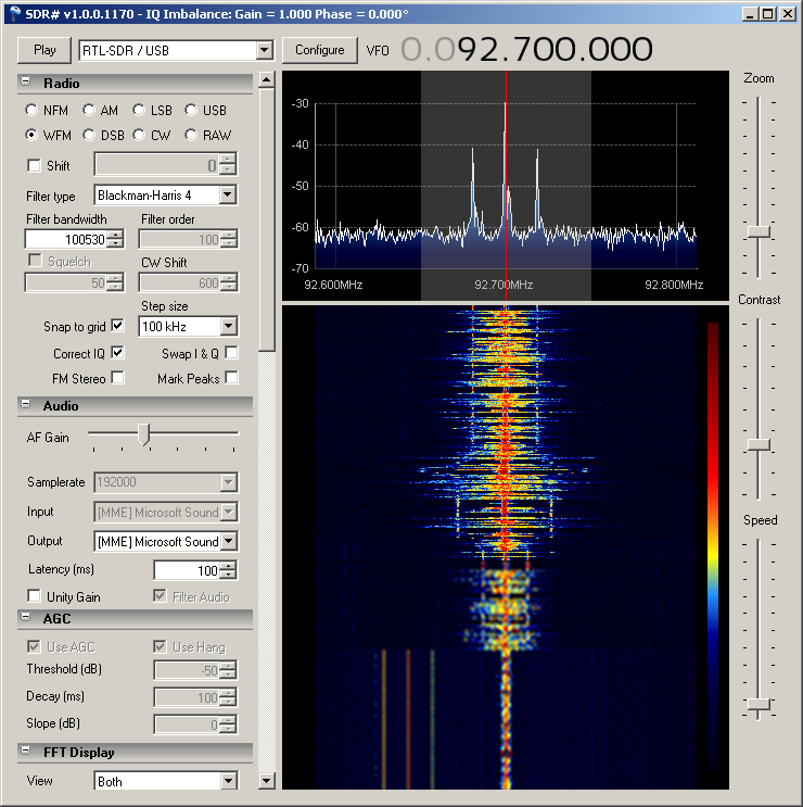
Radio 4 FM spectrum using SDR# with stereo pilot tone clearly visible
Though SDR# is easy to use I think the Windows environment is fairly limited for SDR and if I was starting again I would probably go straight to Linux. Most of the serious SDR tools are primarily developed for Linux.
Having seen what looked like GSM BCCHs I was really keen to try and decode them. I found this guide which I basically followed. I didn’t want to set up a dedicated machine for SDR so I decided to go down the virtual machine route. I installed the free version of VMware player and installed Kali Linux version 1.0.5. Though Kali Linux download page has an image for VMware it is an old version so I created a new VM and installed 1.0.5 from the ISO. This was very easy. Version 1.0.5 has many SDR tools already installed and as many of the tools seem difficult to install this is a significant advantage. I was very impressed with the performance of VMware player and the ease with which it was possible to connect the USB dongle.
Having created the virtual machine I followed the recipe linked above to decode the GSM broadcast channel. If you start from version 1.0.5 you don’t need to install GNU radio but when you install Airprobe you will need to add the additional dependencies as explained in the recipe. The only issue I found was that apt-get didn’t like the “-y” option so omit this from the dependency install and manually accept the installation.
The Airprobe tool used to decode the GSM BCCH seems pretty buggy and is still a work in progress. Though it has a GUI it doesn’t appear to respond to any clicks in my version so you need to set everything from the command line. The command I used was:
./gsm_receive_rtl.py -s 1e6 –f 948000000
948000000 is the frequency of the GSM BCCH I found using SDR# in Hz. You can see GSM downlink channels as fairly broad peaks around 900MHz in SDR#. Check the downlink centre frequencies used by GSM to get the exact centre for any candidate.
I immediately started getting decoded GSM cell data from Airprobe, but it seems to quickly loose sync or tuning and stop producing output. I suspect there is some kind of bug in its tracking algorithm, but it could also be a peculiarity of my configuration. When the program gets stuck use control-C in the starting terminal to kill it.
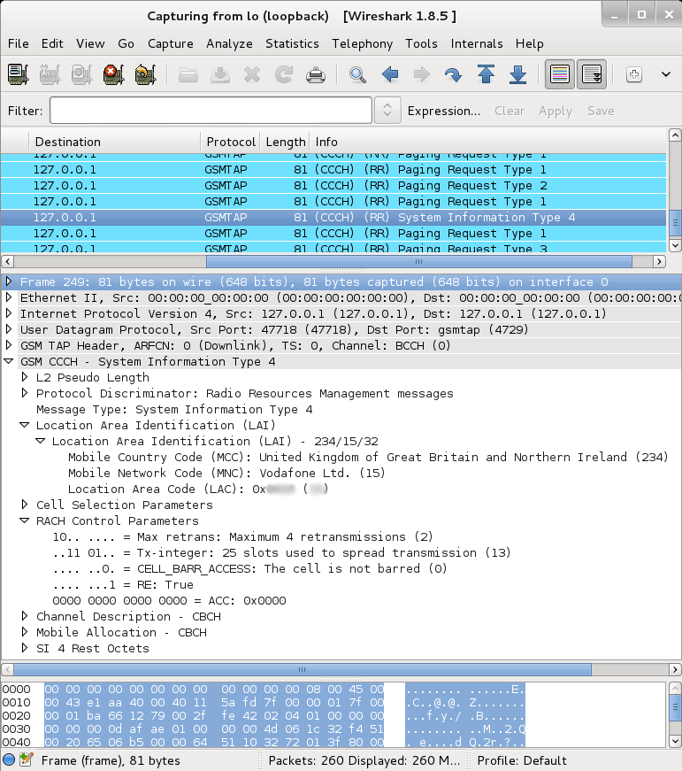
GSM BCCH decoded using wireshark
Anyway, for £12.50 and a load of free software I think the ability to receive GSM cells is pretty impressive.
-
Spectrum Analysis in 1986
Posted on November 17th, 2013 No commentsI have heard that when you use a tool your brain treats it like an extension of the body and, effectively, it becomes part of you. I don’t know if this applies to electronic test equipment, but certainly some of my strongest memories of learning practical electronics are the equipment I used in different periods.
In 1986 I joined the Communications Lab at GEC Research as a student apprentice, or “intern” as people would probably say now. It turned out to be a fateful decision because I worked on early trials for the GSM cellular system and that defined the future direction of my career. The labs were proper research spaces with long wooden benches and lots of hand-made hardware which was cutting edge for the date. They also had a lot of fancy test equipment.
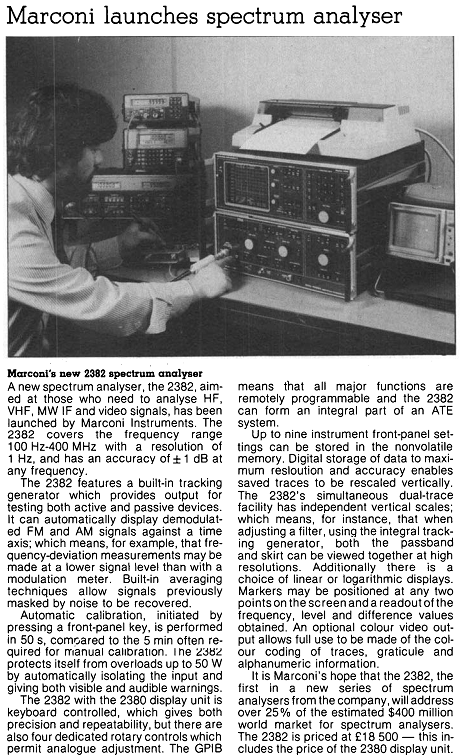
We had a raft of impressive Tek mainframe scopes on trolleys, but sometimes more exotic equipment was needed. Doing radio work a spectrum analyzer comes in handy and the most common one around the site was the Marconi Instruments 2382. Marconi was part of GEC so it made sense to buy in the family, but I think Marconi had genuinely produced a product that had a price/performance ratio that lead the industry. Using a computer-driven display (controlled by the good old 8085 CPU) to replace the storage-tube traditionally used for spectrum analyzers reduced costs and provided exciting features like GP-IB based plotter output.
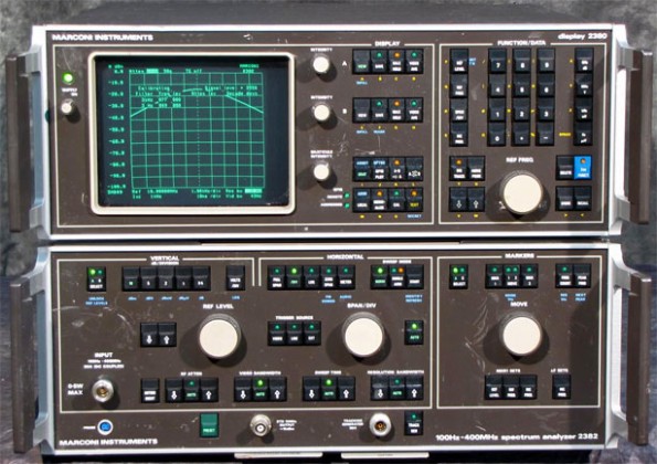
Marconi2382 Spectrum Analyzer
The 2382 was a massive instrument of two brown boxes for the analyzer and the display. The combination was a foot tall (30cm) and nearly 2 feet deep. It was build like a tank. I am pretty sure that if it fell on you it would probably kill you. The controls included a vast field of clicky switches with embedded LEDs (no membrane keyboards for this monster). In fact my recollection of operating the device involves a lot of clicking. It had some kind of internal relay-driven attenuator and some operations would unleash vast sequences of clicks from the interior.
I think the 2382 was regarded as pretty cheap for what it did. This piece from IEEE Electronics and Power in May 1985 says the prices start at £18,500. £18,500 in 1985! Probably enough for a small house.
Learning to drive the 2382 was not just about learning to navigate its many controls. It also taught me a lot about how radio works in practice. Just looking at FM stations gave you a real visual model of ideas like noise, sidebands and carriers.
Despite it’s bulk and cost the 2382 had one major problem – a maximum operating frequency of 400MHz. Not enough for us to use it on the GSM baseband operating at 900MHz and pretty limiting for a lot of comms use. In the comms lab we often had to use even more expensive and exotic HP Analyzers. HP was pioneering the use of screen-menu driven interfaces so though their stuff was the bees knees it never matched the 2382 in terms of button-load shock and awe.
For those that want to dig deeper, try the Marconi 2382 Data Sheet, or the service manual for the RF unit.
-
PCB Layout Tools – I am a KiCAD fan
Posted on September 24th, 2013 No commentsFrom the postbag:
Was thinking about a project building front panels for various DIY synth projects out of PCB material and mounting all the control components (pots, switches) on the PCB itself like on the Lush (eliminating most of the point to point wiring). What PCB design package do you use and how difficult was it to learn?
Tom
Dear Tom,
As I’ve said elsewhere I hate point-to-point wiring so I made it a feature of LushOne to have all the components mounted on the board. I had previously used Eagle but the LushOne the board was too big for the low-cost edition. In any case, I like to use open source software when I can even though a lot of it is not that user-friendly. The LushOne was the 1st project I laid out in KiCAD and I’ve actually found it a really effective design tool.
Like all CAD systems it has a bit of a learning curve, but generally I’ve found it easier to use than Eagle. It’s not as powerful as Eagle and lacks the scripting capabilities but it is perfectly adequate for my projects.
The worst part of KiCAD is the Gerber viewer. I tend to use the online Gerber viewers like the one at OSHPark.