

-
LushOne Base – High pass filter mod
Posted on June 20th, 2013 No comments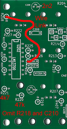
Changes to convert the LushOne Base filter from low-pass to high-pass
Once the LushOne had a fairly complete set of basic synthesizer functions available I always intended to built a powerful multi-oscillator and multi-filter system. You may laugh, but in the back of my mind I had the brief-case sized systems built on the boutique Mattson Mini Modular components.
Once you start thinking about building a full system then you are going to want a high pass filter option to complement the low pass filter in the LushOne Base. Fortunately it is easy to modify the LushOne Base filter to be high pass instead of low pass. Here are the changes:
- Omit R218 and C210 and instead link the two footprints with a wire as shown on the left.
- Change the value of C208 to 2.2nF. This is the same value as C210 so you can do a substitution there. Obviously this capacitor is now non-polar so ignore the polarity markings on the PCB.
- Change R221 to 4.7k
- Change R220 to 47k
That’s all there is to it! Sit back and enjoy some new sounds.
Generally the low pass filter is more useful so if you only have one LushOne Base then I wouldn’t make this a permanent change. However if you want to build a system with more than one LushOne base, or if you want to take the LushOne Base schematic and build your own filter on vero-board then it’s well worth having a high pass option.
If you are using both the filters I recommend putting the high pass first in the signal path and then the low pass. This will reduce the risk of any high-frequency noise getting though in to the output. This arrangement can produce quite natural sounding instruments from the LushOne oscillators.
Remember that with both a high pass and a low pass filter it is rather easy to cut the signal off all together by having non-overlapping filter bands!
Here’s a little multi-tracked sample from a dual-filter LushOne:
-
Equation for op-amp sum/difference amps
Posted on June 2nd, 2013 No commentsWarning: this post contains maths
I can never find on the web or in my text books the general equations for op-amps used as combined multi-input summing and difference amplifiers (ie they have several positive and negative inputs). It makes designing mixers for synthesizers annoyingly awkward as I have to rederive the equations each time. So, to save myself having to work everything out from scratch again, here are my derivations and notes on multi-input Op-Amp circuits. I will also take the opportunity to point out some interesting parts of the results.
Main Results
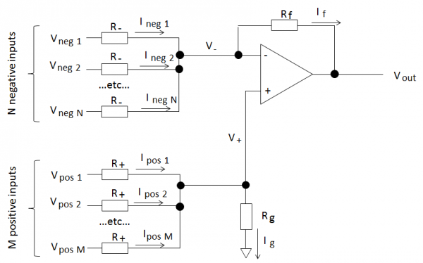
So, here’s the setup:
We have an op-amp circuit with “N” negative inputs and “M” positive inputs as shown above. All the positive and negative inputs are identical.
For an ideal op-amp the output is:
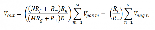
Or, in other words the negative gain is:
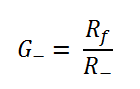
The positive gain is:
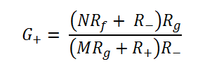
Positive and negative gain
The negative gain is nice and easy and only depends on the input and feedback resistors and not on any other variables, like the number of inputs. Why is this? Well the inverting input of the op-amp is a virtual ground and the voltage isn’t changed by the negative inputs. Therefore the current through each negative input only depends on its input voltage. You can have as many or as few negative inputs as you like and it works the same.
The positive inputs are not in this lucky position! Voltages at the positive inputs change the voltage at both the inverting and non-inverting inputs of the op-amp. The non-inverting input voltage changes because of the voltage drop over Rg. The inverting input voltage changes due to the feedback action of the op-amp keeping the input voltages ideally identical. This means that currents flowing through all the input branches depend on the positive input voltages and hence the complicated positive gain equation.
Limits on positive gain values
Once the negative gain is set, this configuration limits the range of values of the positive gain depending on the number of positive and negative inputs. One particular example:
If the negative gain G- > 1 and number of negative inputs N < M, the number of positive inputs then G+ < G-.To derive this then consider that the maximum positive gain is when the input resistors R+ = 0 (obvious from the circuit and also by inspection of the equation).
Special cases and derivation
There are several interesting special cases from these equations (including the basic op-amp single input amplifiers) and the derivation is worth reading. So I don’t fill the blog with equations you can read it all in this pdf file.