-
Spectrum Analysis and GSM Broadcast Decoding in 2013
Posted on November 17th, 2013 No commentsThis post is about the low-cost SDR systems becoming available. I am afraid it’s not going to be very beginner friendly so I am going to assume that you have a general understanding of radio technology and SDR. In the last post I talked about the massive and expensive spectrum analyzers I used in the 1980s. In fact, even in that era I worked on SDR. Using a PDP 11 we analysed batch files of samples from radar systems to test new processing algorithms.
So why is SDR a hot topic now? Basically a combination of new hardware and the increasing power of desktop PCs has brought powerful SDR solutions within the reach of hobbyists and low budget researchers. There are two main strands:
Firstly, there is what we might call serious low-cost SDR. This consists of hardware boards in the spirit of something like the Arduino or Raspberries Pie which provide experimental but capable SDR platforms in a relatively low-cost package. Typically though these are not what you could call “cheap” as they still may cost hundreds or thousands of pounds. What you get is something with fairly good RF performance and perhaps the possibility of transmitting as well as receiving.
Secondly, there is what we might call seriously-low-cost SDR. This reuses very cheap USB TV receivers as SDR receivers. It is this ultra-low-cost SDR that I am going to talk about here.
My SDR Hardware!
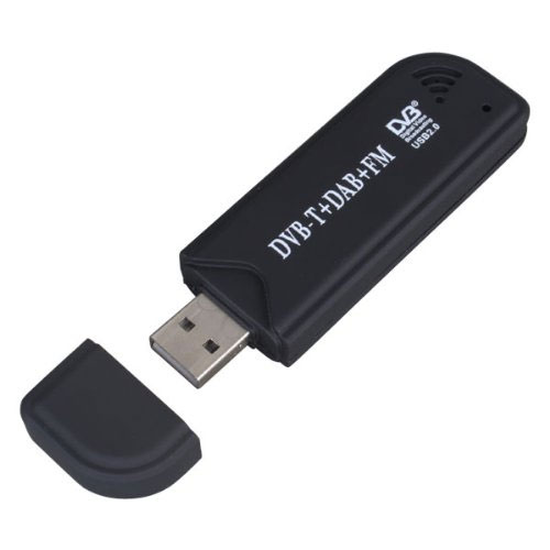
Two key points make ultra-low-cost SDR possible. Firstly it was discovered that certain chipsets widely used in USB TV receivers had a much wider tuning range than was needed for TV. The chipsets can also send the intermediate frequency I and Q samples directly over USB to the host computer. Secondly it was found that the processing power on normal PCs was sufficient to perform, in real time, SDR functions on the I and Q samples coming from the USB receiver.
I bought a dongle based on the RTL2832U+R820T chipset from Amazon for £12.50. This was a slight mistake as it was despatched from the Far East and took several weeks to arrive so my first advice would be to order locally. So what does a cheap USB TV receiver like this provide in terms of performance? According to this very useful stream of consciousness this chipset can tune from 24 – 1700 MHz. That covers FM, ham radio and GSM. It uses a 3.57 MHz intermediate frequency and has a tuning error of perhaps 30 ppm which is relatively stable for a particular dongle when it is warm.
The intermediate frequency sampling is 8-bit and around 2MS/s is an achievable sampling rate. The dynamic range is about 45 dB. My experience is that the biggest problem is various spurious signals appearing that seem to by primarily due to interference at the intermediate frequency. There are various homebrew solutions to improve screening described on the web but I haven’t tried these.
My 1st experiment was using SDR# running on Windows. This was easy to install using a recipe I found on the web. I just hooked up a few meters of wire to use as an antenna. I was easily able to scan the FM and air bands to receive various stations. Once the “Correct IQ” option was checked I was able to receive sounds. I also looked around 900 MHz and saw what I thought were probably GSM cells. It’s not really fair to compare my 2013 technology to the spectrum analyzers of 1986, but as a way of visualising common radio signals it serves the same purpose for 0.07% of the cost (less allowing for inflation)! On its own I find this fascinating.
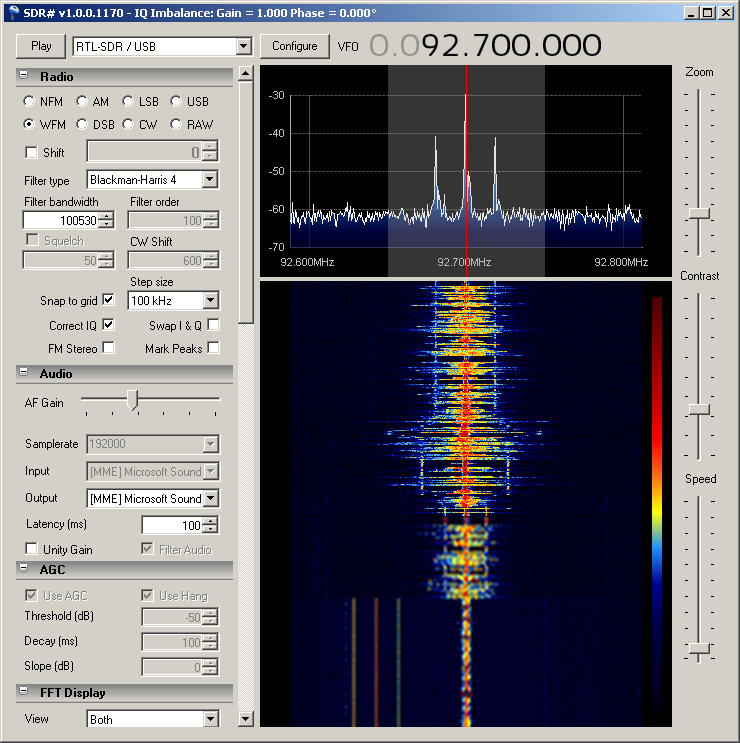
Radio 4 FM spectrum using SDR# with stereo pilot tone clearly visible
Though SDR# is easy to use I think the Windows environment is fairly limited for SDR and if I was starting again I would probably go straight to Linux. Most of the serious SDR tools are primarily developed for Linux.
Having seen what looked like GSM BCCHs I was really keen to try and decode them. I found this guide which I basically followed. I didn’t want to set up a dedicated machine for SDR so I decided to go down the virtual machine route. I installed the free version of VMware player and installed Kali Linux version 1.0.5. Though Kali Linux download page has an image for VMware it is an old version so I created a new VM and installed 1.0.5 from the ISO. This was very easy. Version 1.0.5 has many SDR tools already installed and as many of the tools seem difficult to install this is a significant advantage. I was very impressed with the performance of VMware player and the ease with which it was possible to connect the USB dongle.
Having created the virtual machine I followed the recipe linked above to decode the GSM broadcast channel. If you start from version 1.0.5 you don’t need to install GNU radio but when you install Airprobe you will need to add the additional dependencies as explained in the recipe. The only issue I found was that apt-get didn’t like the “-y” option so omit this from the dependency install and manually accept the installation.
The Airprobe tool used to decode the GSM BCCH seems pretty buggy and is still a work in progress. Though it has a GUI it doesn’t appear to respond to any clicks in my version so you need to set everything from the command line. The command I used was:
./gsm_receive_rtl.py -s 1e6 –f 948000000
948000000 is the frequency of the GSM BCCH I found using SDR# in Hz. You can see GSM downlink channels as fairly broad peaks around 900MHz in SDR#. Check the downlink centre frequencies used by GSM to get the exact centre for any candidate.
I immediately started getting decoded GSM cell data from Airprobe, but it seems to quickly loose sync or tuning and stop producing output. I suspect there is some kind of bug in its tracking algorithm, but it could also be a peculiarity of my configuration. When the program gets stuck use control-C in the starting terminal to kill it.
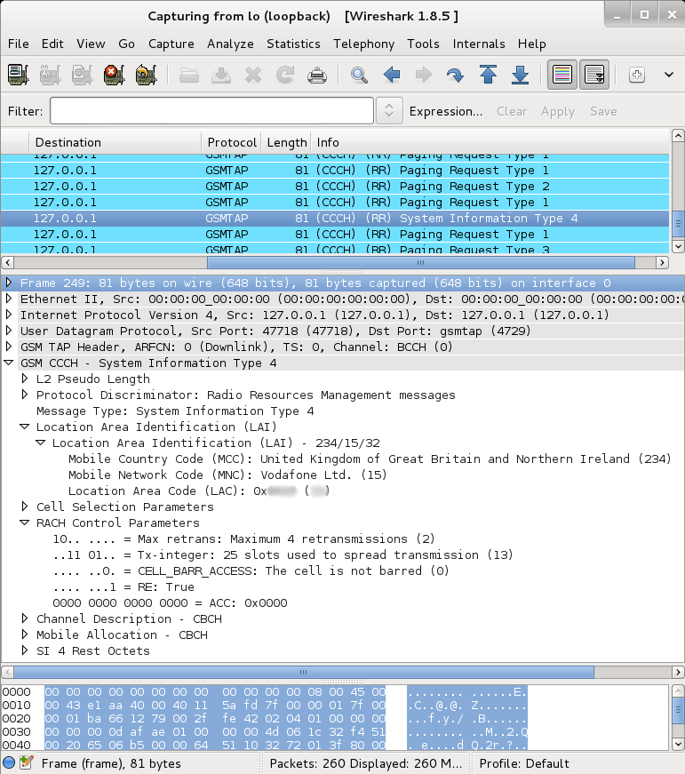
GSM BCCH decoded using wireshark
Anyway, for £12.50 and a load of free software I think the ability to receive GSM cells is pretty impressive.
-
Spectrum Analysis in 1986
Posted on November 17th, 2013 No commentsI have heard that when you use a tool your brain treats it like an extension of the body and, effectively, it becomes part of you. I don’t know if this applies to electronic test equipment, but certainly some of my strongest memories of learning practical electronics are the equipment I used in different periods.
In 1986 I joined the Communications Lab at GEC Research as a student apprentice, or “intern” as people would probably say now. It turned out to be a fateful decision because I worked on early trials for the GSM cellular system and that defined the future direction of my career. The labs were proper research spaces with long wooden benches and lots of hand-made hardware which was cutting edge for the date. They also had a lot of fancy test equipment.
We had a raft of impressive Tek mainframe scopes on trolleys, but sometimes more exotic equipment was needed. Doing radio work a spectrum analyzer comes in handy and the most common one around the site was the Marconi Instruments 2382. Marconi was part of GEC so it made sense to buy in the family, but I think Marconi had genuinely produced a product that had a price/performance ratio that lead the industry. Using a computer-driven display (controlled by the good old 8085 CPU) to replace the storage-tube traditionally used for spectrum analyzers reduced costs and provided exciting features like GP-IB based plotter output.
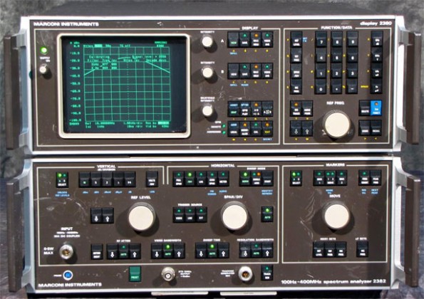
Marconi2382 Spectrum Analyzer
The 2382 was a massive instrument of two brown boxes for the analyzer and the display. The combination was a foot tall (30cm) and nearly 2 feet deep. It was build like a tank. I am pretty sure that if it fell on you it would probably kill you. The controls included a vast field of clicky switches with embedded LEDs (no membrane keyboards for this monster). In fact my recollection of operating the device involves a lot of clicking. It had some kind of internal relay-driven attenuator and some operations would unleash vast sequences of clicks from the interior.
I think the 2382 was regarded as pretty cheap for what it did. This piece from IEEE Electronics and Power in May 1985 says the prices start at £18,500. £18,500 in 1985! Probably enough for a small house.
Learning to drive the 2382 was not just about learning to navigate its many controls. It also taught me a lot about how radio works in practice. Just looking at FM stations gave you a real visual model of ideas like noise, sidebands and carriers.
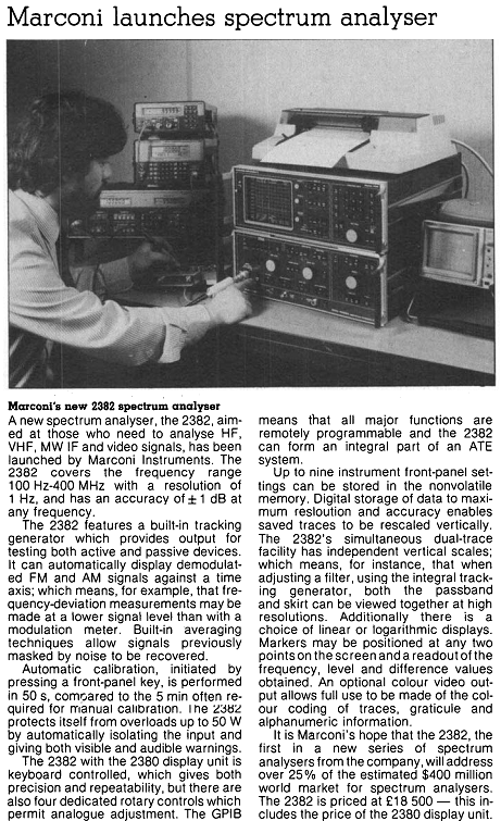
Despite it’s bulk and cost the 2382 had one major problem – a maximum operating frequency of 400MHz. Not enough for us to use it on the GSM baseband operating at 900MHz and pretty limiting for a lot of comms use. In the comms lab we often had to use even more expensive and exotic HP Analyzers. HP was pioneering the use of screen-menu driven interfaces so though their stuff was the bees knees it never matched the 2382 in terms of button-load shock and awe.
For those that want to dig deeper, try the Marconi 2382 Data Sheet, or the service manual for the RF unit.
-
Azymbol from Belgium – LushOne case builder extraordinaire
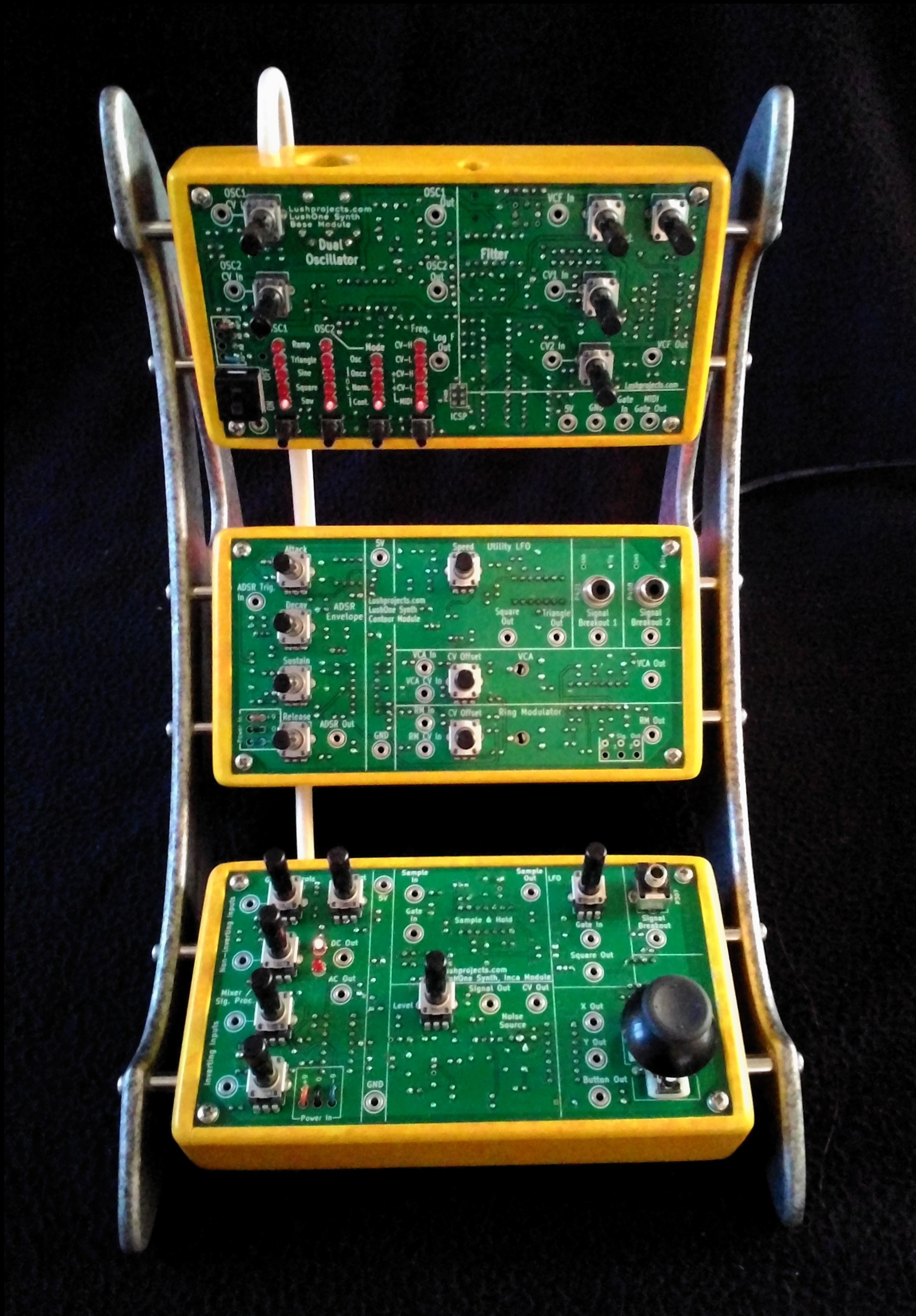
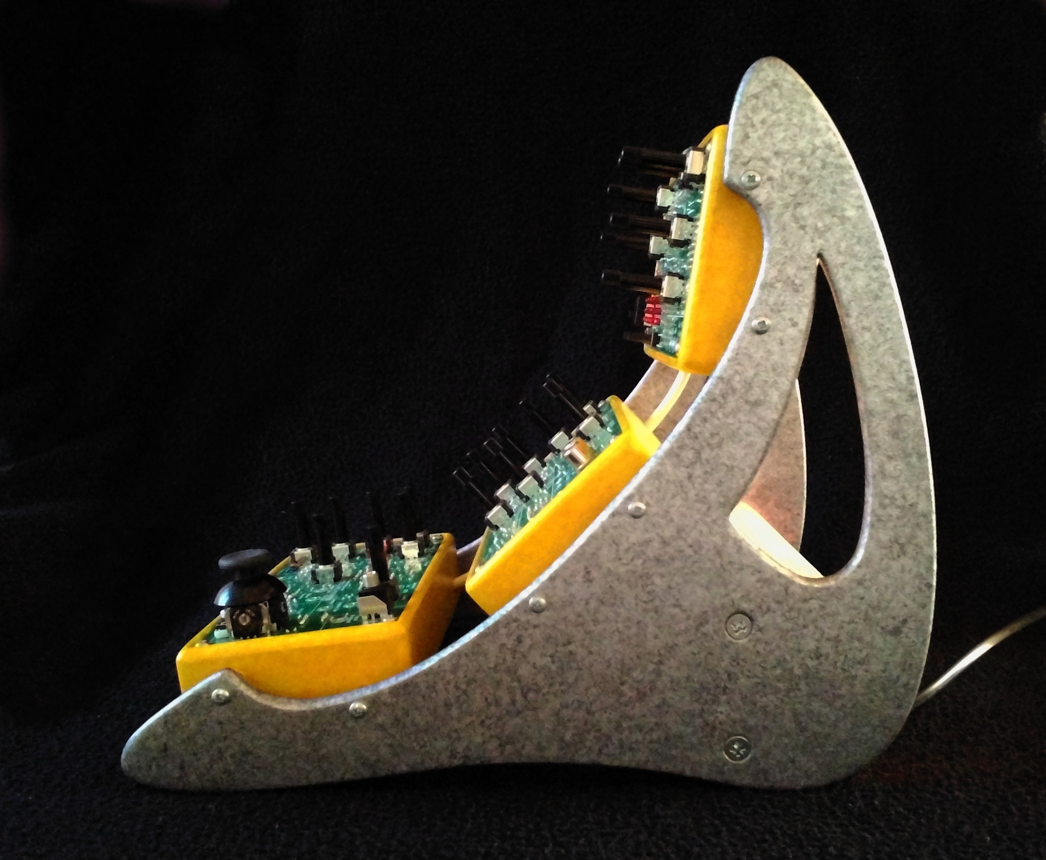
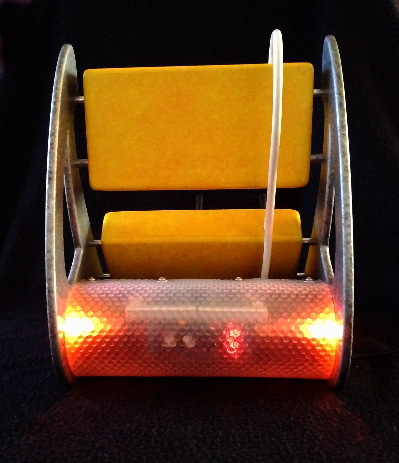
Posted on November 16th, 2013 No commentsOne of the joys of running LushProjects is seeing some of the imaginative work that people put in to building cases for my circuits. Recently Azymbol from Belgium sent me some photos of his LushOne system case which breaks new ground in design and craftsmanship.
Working in MDF and recycled materials including placemats and tennis ball tins Azymbol has created a design that evokes 60s futurism displaying the controls to maximum advantage on a dramatically curved frame. The colour is applied in acrylic paint and creates carefully judged dramatic contrasts.
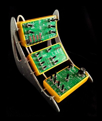
Azymbol LushOne
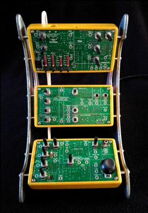
Azymbol LushOne Front

Azymbol LushOne Side

Azymbol LushOne Back
Technically Azymbol has used the LushOne base, Contour and Inca modules to build the synth and a Velleman P8042 symmetric power supply he sourced himself.
The design and build are magnificent. Bravo!