Lushprojects Blog
Projects in music, video, art, technology and learning

-
Cheap as Chips Logic Analyzers in 2026
Posted on February 15th, 2026 No comments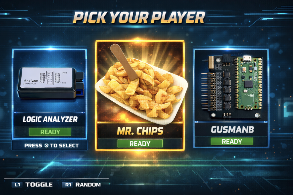
The first logic analyzers I used were behemoths from the old-style HP. They were physically daunting, brutally expensive, and massively complex. Now you can get PC-based logic analyzers from eBay and Aliexpress for a few quid which still offer amazing capabilities.
I recently killed my Saleae 8 clone when a visible spark jumped to the probe while I was connecting it to the test circuit (never a good sign). Looking for a replacement I found a couple of new options. Here are my thoughts on some of the cheapest logic analyzers you can buy.
Saleae 8 Clones
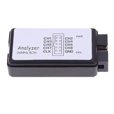
There are lots of these around and they are very cheap indeed (<£10 for two). At that price it wasn’t a tragedy when mine got zapped. They provide eight digital inputs and don’t store any data locally – they just stream it back to the host PC over USB. With no memory limits in the device you can make very long captures and they can still achieve a very respectable 24MS/s in Pulseview.
These are excellent value for money and they are still my go-to solution for most use-cases.
I prefer Pulseview from the Sigrok project over the Saleae software, but one thing to know about Pulseview is that the official Release version (0.4.2) seems frozen in time. The nightly version is much better and has useful new features.
Gusmanb Logic Analyzer
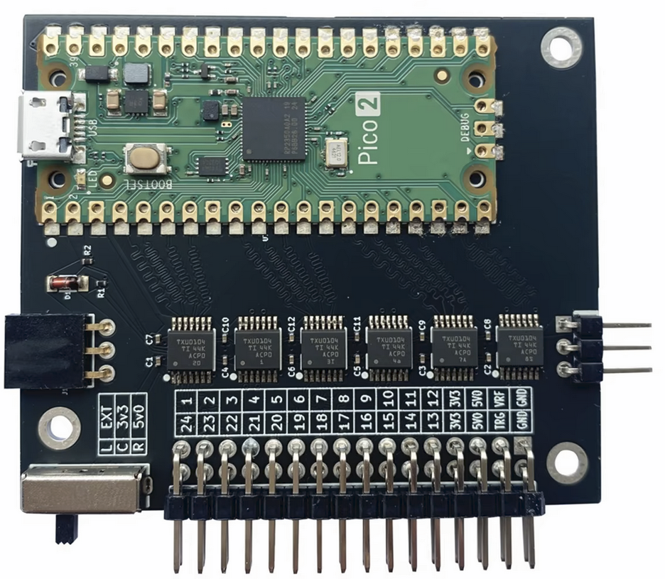
The Gusmanb Logic Analyzer (hereafter “Gusmanb”) is the new option that caught my eye. It is an open source project consisting of a simple hardware module and a PC application. The v2 hardware is a Pi Pico 2 frontended by level-shifters. The PC application is new but can use Pulseview decoders.
The hardware has a switch to select between 5V, 3.3V or user-defined logic levels. There are 24 inputs, but multiple units can be daisy-chained to provide more inputs (something I haven’t tested). What is different from the Saleae clones is that the real-time data collection is stored on the Pi Pico 2 and then transferred to the host after the collection has happened. This limits the amount of data you can collect on each capture to what will fit in the Pi Pico 2’s RAM but allows high sample rates.
With the default firmware the hardware can capture at a configurable rate of up to 100MS/s in normal mode or a fixed rate of 200MS/s in “blast” mode. There is also a “turbo” version of the firmware which overvolts and overclocks the Pi Pico 2, I assume to achieve higher sample rates (I haven’t tested this).
The memory-bound capture size feels like a limitation but this is somewhat offset by the ability to flexibly configure triggers (again I haven’t tested this) and the ability to automatically retrigger to capture multiple events.
The PC application is OK, but the user experience and capabilities can feel a little inconvenient and immature compared to Pulseview. Being able to use the Pulseview decoders is a big plus though – it provides immediate access to all the popular protocols.
Gusmanb with Pulseview/Sigrok Firmware
Pulseview has recently added its own support for using a Pi Pico as a capture device (you need the nightly version to enable this).The Pulseview firmware can work both using local capture (limited by memory) and streaming mode (limited by USB bandwidth). That is potentially a very flexible solution. The interesting thing for me is that the Gusmanb hardware should be compatible with the Pulseview Pi Pico firmware so you should be able to choose which system to go with by changing the firmware image.
The Pulseview Pi Pico firmware mainly targets the original Pi Pico (using the RP2040). The main repo does contain a version that claims to support Pi Pico 2 (using the RP2350) but that didn’t work in my testing. If you run into the same problem you can try this fork of the Pulseview firmware which did work with my Gusmanb hardware even though there isn’t any visible reason to explain why one works and the other didn’t.
In this combination you do need to be aware of the performance limits which are detailed in the repo. You may also need to work around some buggy behaviour of the Pulseview serial driver (again see notes in the repo).
Conclusion
The Saleae 8 Clones are great value for money and work well for most of my embedded use-cases. I think that will continue to be my primary option.
The Gusmanb project is an interesting new solution and an impressive achievement for a one-man DIY project. It has some well thought-out features like the selectable logic voltage which I really like. I see it as a useful tool for when I need more than 8 channels or want proper control over the logic levels being used. For retro-computing where you have big parallel buses this could be particularly relevant. The biggest gotcha is the memory limit and you might need to carefully specify triggers to capture what you want. Hopefully we’ll see more development of the PC application either by the original author or other contributors.
Using the Gusmanb hardware with Puleview/Sigrok firmware does seem to be a workable option though with the performance limits I don’t see it is a good solution for my use cases.
There are a lot of RP2350 boards with extra PSRAM. If anybody wants a project idea those might offer interesting capabilities for large, fast, captures with suitable firmware.
All these options are cheaper than a fish supper and for that you get a logic analyser which is more than good enough for embedded and retro use cases. I find that incredible!
-
“Radio and Television” from the Macdonald Junior Reference Library
Posted on February 16th, 2025 No commentsAn old childhood book I found recently was “Radio and Television” from the Macdonald Junior Reference Library. Published in 1969, my copy was the 1972 reprint. It cost 45p new, but mine was bought for 20p in 1979 when it was withdrawn from stock at Rutland library.
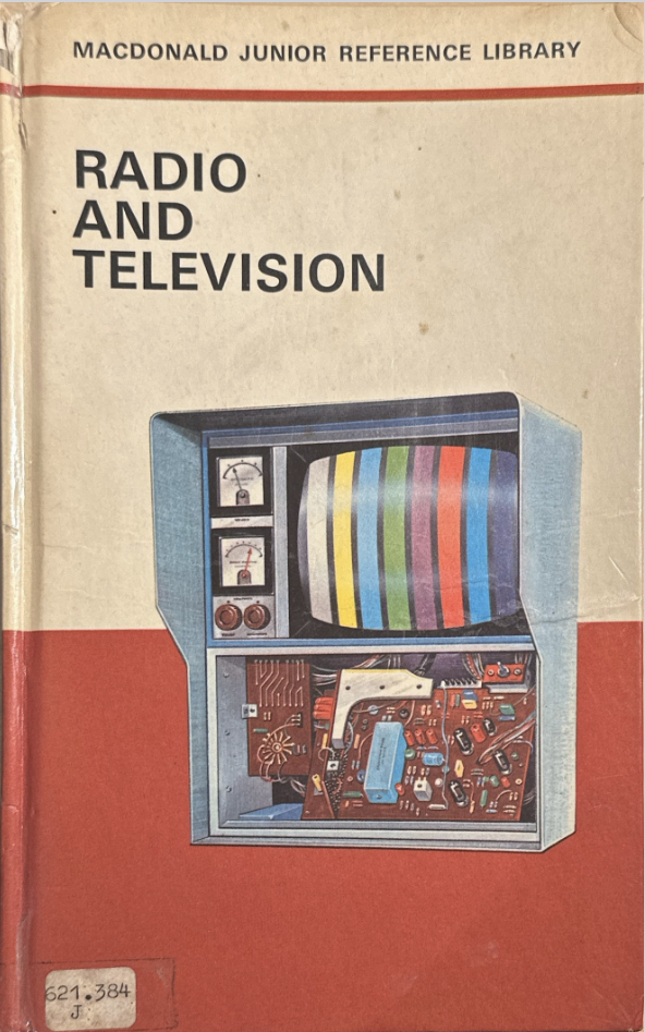
Front Cover of Radio and Television The illustrations are really nice. The text is mostly an encyclopedia style collection of terms related to radio and television technology. The terms are alphabetically sorted and seem to have been somewhat randomly chosen.
There is a big mistake on page 43 in the example of resistors in parallel. That was obvious to me when I looked through the book as an adult. I am surprised that the editors didn’t notice.
I remember even as a child I liked the look of the book, but was disappointed by the limits of the encyclopedia format.
-
Hantek6022BE USB Scope + OpenHantek6022 Fills a Useful Niche
Posted on December 29th, 2022 No commentsI’ve been looking for a scope that can be always on my bench for making quick assessments of circuits running at low frequencies. My electronics bench is also my work desk, so space is very much at a premium. My full-size analog and digital scopes are too big to leave set up there permanently (PS, a personal annoyance with modern digital scopes is that their shape means you can’t stack other equipment on top of them). I do have a little DSO Shell kit-scope which is OK, but a bit fiddly to operate and only has a single, very low frequency, channel.
There are of course various handheld scopes and scope-meters on the market, and maybe they would be a good option, but they need to be positioned in prime desk space to reach, and that would be awkward for me.
So far, my Sinclair/Thandar SC110A has been the best bet, but the small screen means it needs to be carefully adjusted to get a good view of a signal, and that’s not helpful when you are probing around a circuit.
I did look at other small analog scopes (I like analog for quick exploratory tests), but didn’t find anything that had a combination of price, size and capabilities that worked for me.
I started to wonder if I wasn’t better off going a different route and instead of looking for a small scope, I should make use of the PC and 4K monitor that’s always part of my workstation. I’ve resisted PC scopes on the assumption that the software will be grim, and the whole experience will be klunky. I’ve not had a good experience with test equipment integration with computers since using HP-IB and HP Basic to automate test systems back in the 1980s.
However, I was intrigued when I saw a cheap Hantek6022BE scope on eBay, and finding out that there is a well-liked, lightweight, and Open Source software platform for it. It was cheap enough that I was willing to give it a go and see whether this device could become my everyday scope.
When the unit came I was impressed. The box that needs to sit on the desk is fairly small, and can be easily tucked-away. It can even be stood in its side for a smaller footprint. Getting the open source drivers and OpenHantek6022 application installed was easy on Windows 10 using the instructions on the GitHub ReadMe. OpenHantek6022 has a level of maturity not often seen on niche open source applications. In particular, the documentation is very comprehensive.
In use I find the combination of hardware and software basic, but effective. OpenHantek6022 is very usable, though there are a few UI things I would tweak. Everything is visible and you don’t have the feeling of “menu diving” like you do on a lot of digital scopes. It’s also very responsive (due to a small memory depth I suppose) in a way that feels a lot like an analog scope.
I was also interested to see that the scope was compatible with Sikrok’s Pulseview software. I had some trouble getting the driver installed to work with Pulseview. The 6022 and similar devices have a slightly odd way of managing USB firmware (explained in this video) which can easily trip you up. I found Windows 10 was picking up the wrong driver once Pulseview was run. To get the right driver for Pulseview I had to:
- Start Pulseview with the 6022 connected
- Find the device in the Windows Device Manager
- Right-click and choose Update Driver
- Click “Browser My Computer”
- Click “Let Me Pick From A List of Available Drivers On My Computer”
- Then I was able to choose the driver from the install package. Ignore the warning about the driver not being optimal (or some such wording)
Pulseview ran fine, and might be a useful alternative to OpenHantek6022 if you want to do long captures, or to do protocol decoding on signals. One annoyance is that Pulseview doesn’t seem to allow you to configure x10 probes, so to get the right voltage scale you have to use the probes in the x1 setting. The wrong voltage on the display wouldn’t matter too much, except that having the wrong voltages then messes up the process of protocol decoding by stopping the conversion of analog captures to digital equivalents for further processing.
Overall I think this is a great package at the price. With the open source software it’s no fuss, and super-usable. Great for doing quick checks on circuits, and with the advantages of a big display I can even see myself using it for more demanding measurements.
EDIT TO ADD:
One potentially serious disadvantage of the 6022 is that the ground terminals are connected to the ground on your PC. If you connect the probe’s ground lead to something at a different voltage then there is a risk of damage to at least the USB port and potentially the whole PC.
For me, this is a risk I can live with, but it does depend on your use-cases, experience, and approach to risk whether this is an acceptable situation. It’s certainly something to consider.
-
My Old BBC Micro
Posted on August 24th, 2022 No commentsAfter a trip “down south” I recovered by old BBC from the loft recently.
It started life as a Model A and was then upgraded to a B, and later a disk interface was added. It also has a big “Sidewise” ROM/RAM board fitted. (My dad was an IT manager for British Gas and was a big believer in upgradability. He approached buying and owning a home computer with about the same attitude as procuring a mainframe for BG. To be totally fair, that strategy did work very well. We got a huge amount of use out of the Beeb over many years.).
Anyway, it’s somewhat dirty but the plastics are in good condition. It’s quite an early board with plenty of factory bodges – the most exciting of which is a variable capacitor trimmer on a bit of veroboard randomly above an IC. The original OS was 0.1, but it was upgraded to 1.2 when that came out.
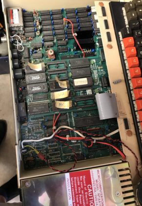
After replacing the usual suspects in the PSU and reseating the expansion board (a problem I remember back in the day) it came straight back to life. Looking at the bodges it’s surprising it worked at all, never mind after all this time. The Cub is a recent purchase BTW, back in the day we had a Philips portable TV with RGB input on the back.
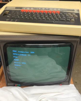
Quite a few ROMs in it – some even legitimate (ISO Pascal, Wordwise). I don’t remember how Basic got upgraded to Basic 2. The more unusual ROMs uinclude PHX (Phoenix) which was a special terminal emulator used by Cambridge Uni and a few others in the UK. It implemented a page editing protocol. I have an odd personal connection to that as I ended up making the official port of the protocol to the Mac 68k era. SSMP is some other kind of terminal emulator (not the messaging protocol), but I don’t remember what I used that for.
Disks and disk drive are currently MIA – possibly still at my dads.
-
Metronome from an Event Badge
Posted on May 3rd, 2021 No comments
Did I mention that I am learning to play the piano? When I started reading music I expected the hard part will be recognising the notes, but with practice I’ve got that fairly sorted. The consistently hard part is recognising the rhythms and being able to play them right. I found having a metronome or drum track really helps with rhythm practice.
I’ve been a bit frustrated that none of the metronome options I found were quite what I wanted. There are 1001 apps of course, offering many features, but I find them a bit painful to configure how I want, and the UIs often trade gloss for practicality. Plus, somehow having my phone in front of me when I am playing isn’t quite nice. Stand-alone metronomes on the other hand seem to be too basic with klunky controls and poor displays. I wanted something that covered 90% of my use cases in a way that was simple, visual and usable.
I also had an unusual requirement that doesn’t seem to be supported in any off-the-shelf solution I could find. I wanted to use a pedal to play the beat myself, but have that mapped on to a drum pattern to help follow the strong and weak beats in a bar.
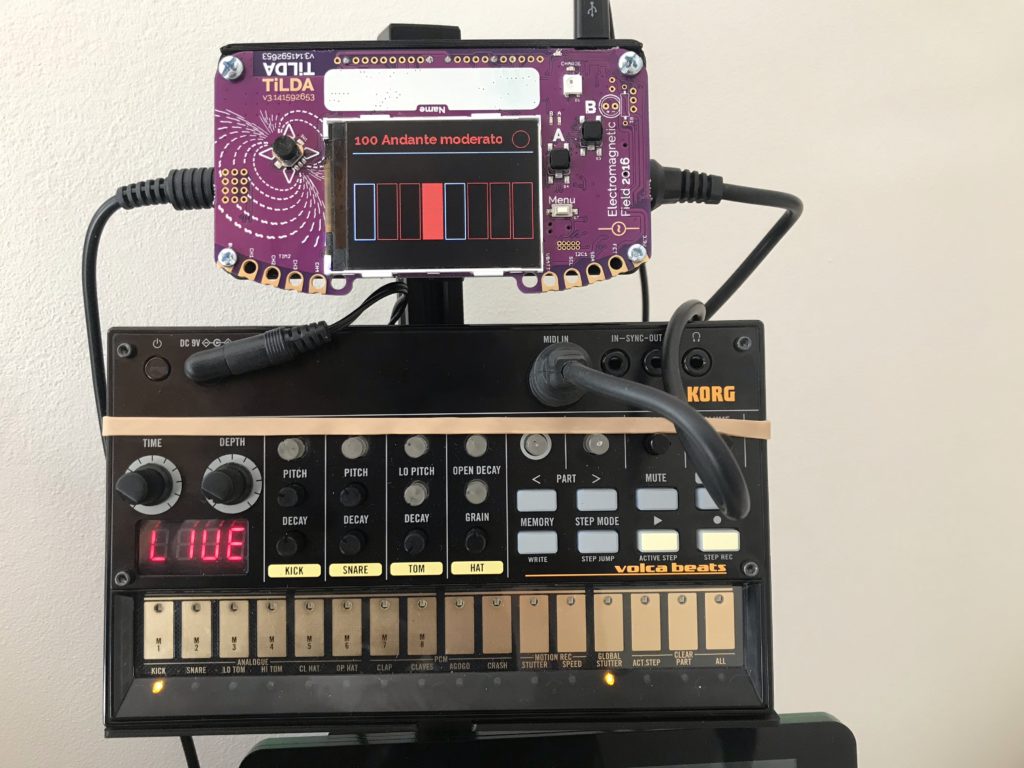
I recently got a Korg Volca Beats (VB) as a way to create easy drum tracks. It’s basic, but fun. It almost passes muster as a metronome too, but again it can be a bit too much effort to configure. My initial goal was to use the sync in signal on the VB to provide a pedal input to step through its sequence. Sounds simple, but in practice it was a nightmare. The VB seems to do some kind of interpolation of the sync in signal and if its slightly irregular it can trigger weird double steps on the sequencer. After a lot of frustration I gave up on that approach.
I went for one last try with an idea to use the MIDI in on the VB to trigger the drums from an external sequencer that could work like a normal metronome or be stepped using a pedal. Like many people I have a box full of development boards from various sources and rather than buy something new I wanted to use one of those. It came down to a ESP8622 board from a Nottingham Hackspace event or the Tilda Badge Mk 3 from EMF Camp 2016. Something had broken compatibility between the current Arduino IDE and the ESP8266 board I had, so I went with the Tilda Badge which turned out to be really well suited to the job.
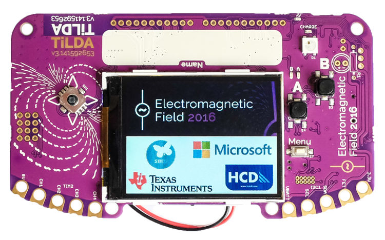
The Tilda Badge Mk 3 The Tilda Badge is programed in Micro Python which is really productive once you get your head round how to use it. The approach I used was different from the ones suggested in the documentation. I connected the badge to my PC which allows it to mount as a mass storage device and as a serial console. Copying a file called “main.py” to the root of the mass storage device creates an application that the Tilda Badge will run on boot. I edited my main.py on the PC and just used a CMD command line to do the copy. To run without resetting the badge, I used this command in the – 115200 BAUD – serial console (courtesy of Stackoverflow):
>>>
exec(open("main.py").read())The advantage of this approach was I didn’t need to install anything special on the PC and I could quickly iterate versions.
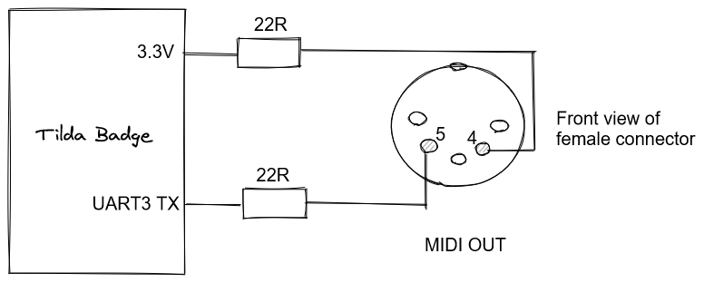
To support a MIDI output I just had to add the simple circuit below to the UART3 TX which is available on the GPIO port of the Tilda Badge. (Note – the pin positions on the DIN connectors used for MIDI are totally confusing. I think this is right, but I would rely on the pin numbers more than the positions in the event of conflict!) The pedal is just connected between the CH1 GPIO pin and ground.
The Tilda Badge turns out to have just the right level of functionality for this application. The connectivity is more than good enough. The display is big and clear enough to show a good visualisation. There are enough buttons to provide easy access to all the services without having to do any “menu diving”.
Software for the Tilda Badge is here (it’s very rough, but does the job).
The finished project integrates in to an accessory system I build with V-slot on the back of my piano stand (that’s another story). I 3D printed a case that attaches the Tilda Badge to the V-slot. It keeps the front of the Tilda Badge PCB fully visible so you can still see its origin, but it protects the back and provides mounting points for the MIDI and pedal sockets.
Overall it is a really pleasing project and it’s nice to find a long-term use for one event badge. It’s fair to say I haven’t been a fan of the trend for electronic event badges – I think a lot quickly become e-waste and they can be a distraction from other parts of the event. But in this case it has been practical as well as cool. It also shows the value of an open, and documented, project that I was still able to pick up the badge after 5 years and immediately start developing on it.
-
BBC Micro on MISTer
Posted on January 24th, 2021 No commentsDuring Covid-19 lockdown one of the things I wanted to do was to revisit some of the old computers I used. I don’t really have the space or inclination so collect the original hardware, so I decided to try out what emulation options exist now.
I have been interested in trying some ASIC based projects, so a natural choice seemed to me to use the MISTer platform. This is a retro computer, console and arcade emulation system based on the DE-10 Nano FPGA development board. This MISTer project was developed from the earlier MIST project which used an older development board.
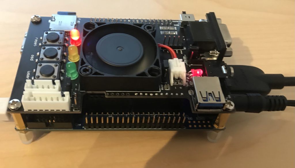
DE-10 Nano with MISTer expansion to support secondary SD Card To get started with MISTer you just need the DE-10 Nano board, but I also chose to get the MISTer add-on board, mostly for the secondary SD Card (more on that later). Most of the emulation cores, but not the BBC Micro, need a RAM add-on board too.
Once you have the DE10 you can just flash the MISTer core on to an SD Card and boot it. You will also need a USB keyboard connected to the “USB to go” socket.
Some useful keys:
CTRL-F11   Break (BBC Micro)
F12        Load MISTer menu
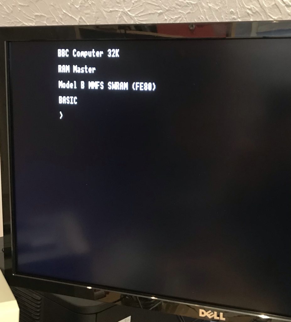
BBC Micro booted using MISTer One limitation of the current core is that it doesn’t support split-mode games like Elite and Revs.
Using BEEB.MMD
The BBC Micro core uses files in “MMB” format. This was a format originally developed for a BBC Micro add-on that connects SD cards to the user port and makes it look like a virtual set of disk-drive. The MMB file is a bundle of hundreds of BBC floppy disk images. Using commands on the BBC Micro you can choose to mount the images from the file in to virtual drives.
The BBC core offers two ways to mount the MMB file. If you have a secondary SD card then format as FAT32 or FAT16. Copy the MMB file as “BEEB.MMB” on to the card. The core will automatically pick up that card. In this mode the file can be both read and written.
The alternative is to rename the file as “.VHD” and copy it to the “games/BBC Micro” directory on the main SD Card. If it is called “boot.vhd” then it will be automatically loaded. If not then you can manually load from the MISTer menu. In this mode the file is read only. To unmount a previously mounted VHD (e.g. to go back to the secondary card) press backspace when picking the VHD.
There are various utilities to manipulate MMB files on PCs. I used “MMBReader” which is available on the stardot forum. On the emulated BBC Micro the MMB file is accessible using MMFS. Note that if no MMB file is available then MMFS will stall the boot of the BBC Micro by displaying the message “CARD?”.
Some useful MMFS Commands:
 *DCAT [start #] [end #]   - List disks in the MMB file
 *DIN [Drive #] <Disk #>   - Mount disk in the specified drive (default 0)
Most of the MMB files you will find on the web are pre-loaded with many original games. By default they boot in to a menu to pick the games. You can disable the autoboot on the first disk by using the command
*OPT 4,0. If you subsequently want to run the boot use*EXEC !BOOT. -
Grid Runner – BBC Micro Juvenilia
Posted on January 20th, 2021 No commentsMy first computer was a BBC Micro Model A (early version with the linear PSU and bodge wires on the circuit board). Later we upgraded it to a Model B. I loved it, and even took it on holiday a few times (!) My parents must have been very understanding.
I was amazed today to discover that the BBC Micro community has saved two very obscure games I wrote in my teens and you can now play them in the browser:
Grid Runner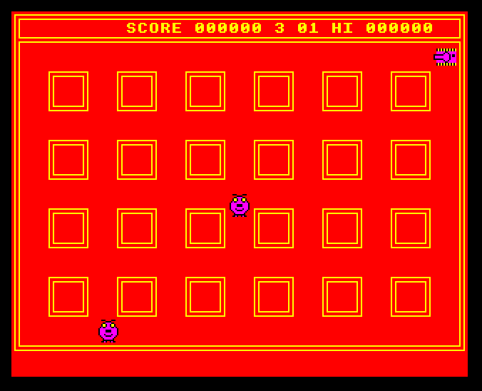
http://www.bbcmicro.co.uk/game.php?id=636
Grid Runner II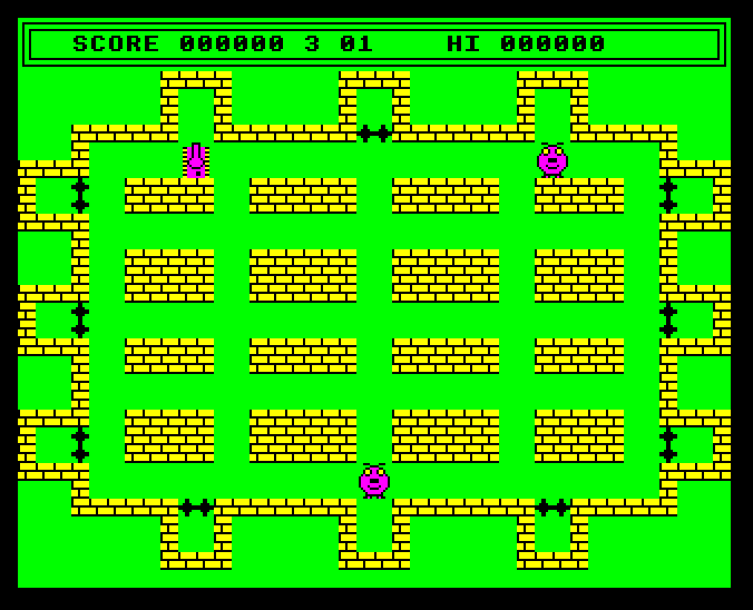
http://www.bbcmicro.co.uk/game.php?id=765
IIRC selling Grid Runner was the first money I ever earned. The BBC Micro magazine Beebug (which was based close to where we live) included it in a demo disk (image via a kind user of the StarDot forums).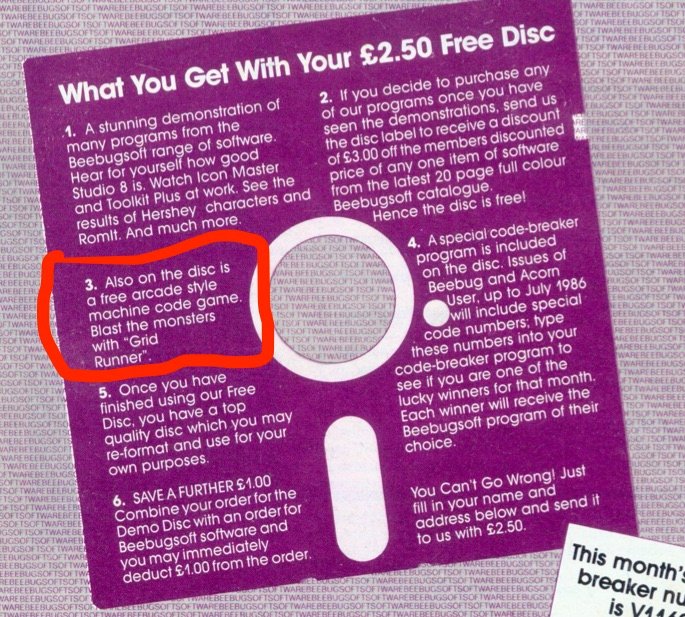
In case you are wondering, I am not colour-blind. The clashing colours were inspired by the BBC classic game Frak.
JS Beeb is fantastic BTW.
-
Networking CATWatch
Posted on December 30th, 2020 No comments(or an overkill solution to tracking the movements of a cat)
I don’t mind cats, but we have one Top Cat (subsequently TC) living locally who thinks he (or she) is the boss of everything. After one too many cat shits and dead birds in our back garden I decided that TC was no longer welcome and was going to be excluded.
Early steps were very simple – filling in the gap under the gate prevented easy access until TC found new ways over the gate and fences. I then decided a more through approach was needed. I installed a Pi Zero W with a night vision camera module (1) running motion project software so I could see whether TC was coming in the garden and perhaps how it was getting in. It works OK with the caveat that the Motion Project software is pretty simplistic in its approach to doing movement detection and even after tuning the parameters I get a lot of false positives. It is a little painful to manually check the output, but that’s OK.
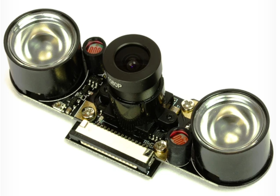
Night Vision Camera Module (before I removed the IR LEDs) I also put in an ultrasonic cat deterrent on the edge of the lawn. This is a passive infra-red (PIR) motion detector linked to an ultrasonic sounder that is supposed to scare cats. There are lots for sale – I used the RSPB CATWatch. It is a battery powered device where motion detected by the PIR triggers an ultrasonic alarm that sounds at about 20kHz for a few seconds. Interestingly, the alarm doesn’t just play a single tone, it varies the tones during the alarm period, presumably to prevent cats getting habituated to the sound.
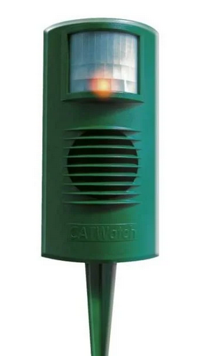
RSPB CATWatch After that we didn’t see TC in the garden for quite a while. We thought the CATWatch probably was scaring it off, though we never caught it in the act. But, one day the camera caught TC strolling around the edge of the lawn, just out of range of the CATWatch PIR detector. Knowing TC was still coming in the garden I followed the example of my neighbour and put cat deterrent spikes around the fence tops, and (so far) we haven’t seen TC again.
But, here is the problem, how do I know TC isn’t coming in any more? The camera sees a lot, but it also misses a lot. Despite its name, the CATWatch doesn’t really watch cats, it just scares them off. In fact you have no way of knowing how often it has been triggered. I wanted a CATWatch extension to log when it was triggering, and ideally to trigger the camera to record too. So, there are two problems:
- How to cause a trigger for the CATWatch to activate an external circuit, and
- How to connect the CATWatch to the Pi Zero without running wires everywhere?
I started thinking about how I could get a wireless signal from the CATWatch to the Pi. My requirements were:
- Simplicity
- Keep the CATWatch battery powered without significant reduction in battery life
- Fast reaction so that the camera will be activated while the cat is still in the vicinity.
The obvious option was WiFi, but keeping that running long-term on a battery is problematic. If you disconnect from the WiFi to save power then reconnecting will add a delay which might not meet the “fast reaction” requirement.
BLE was another option, but the thought of working out the right stack of hardware, libraries, low power modes etc. to make it work made my eye twitch. Modern systems are amazing, but, unless you already know the ecosystem and tools, understanding enough to use it effectively can be a massive PIA.
I realised what I wanted was something very simple, almost primitive, that I could just hook up at each end to send an on/off binary signal. The technology that seemed to fit that best was 433MHz radio remote controls used for garage doors and similar things. I bought a set of 5 key fob transmitters and a 2 channel relay board receiver on ebay. The plan was to put a transistor across one button on the transmitter to send and to remove the relay to get an open collector transistor output on the receiver.
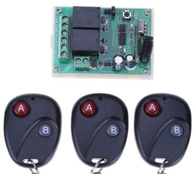
433MHz Receiver Board and Some of the Key Fob Transmitters The receiver board is rated for 12V input, though it worked down to 9V. What I really wanted was for it to be powered off 5V from the Pi. Looking more closely I found, as I expected, that the only part of the circuit that used the 12V was the relay coil. The rest ran on 5V from an internal regulator. I removed the relay and bypassed the power regulation on the board to produce a 433MHz receiver that ran on 5V and could (using an open collector output that originally drove the relay) link to a 3.3V GPIO input on the Pi.
The transmitter fob was very simple – the two buttons just connect a wire to the positive end of the 12V internal battery when pressed. So the only unexpected problem is that I would need to implement a high side switch, rather than a low side switch as I was expecting.
Getting the CATWatch to activate an external circuit would probably be easy, but for one problem: all the electronics are potted in resin except for the power-in and the wires going to the ultrasonic transducer. So, there is no obvious binary “alarm” signal accessible to drive an external circuit. You could trigger based on the ultrasonic output, but I thought it would be easier to use the power input and detect the very marked increase in power consumption that occurs when the alarm is turned on. I put a 15 Ohm shunt in the power line driving a PNP transistor to do the high-side switching for the transmitter (as shown in this simulation). I decided to keep the two circuits on their original batteries, so, to do the high-side switching, these two batteries connected positive to positive as shown.
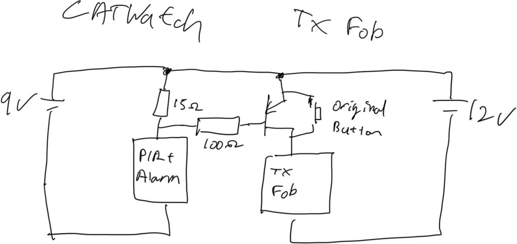
Block Diagram of Connecting CATWatch to the Key Fob Transmitter As always, I hit a snag at the last moment. There was enough space in the CATWatch to include the transmitter fob in the unmodified case, but I found that when the case was closed the alarm wouldn’t turn-off once it had been activated. My suspicion is that the transmitter interferes with some high-Z input that is being driven by the PIR and the circuit keeps thinking it is detecting new motion. So, I 3D printed a “back-pack” that contains the fob circuit and can be attached to the back of the CATWatch away from its electronics. That worked fine and also makes it easier to change the fob battery if needed.
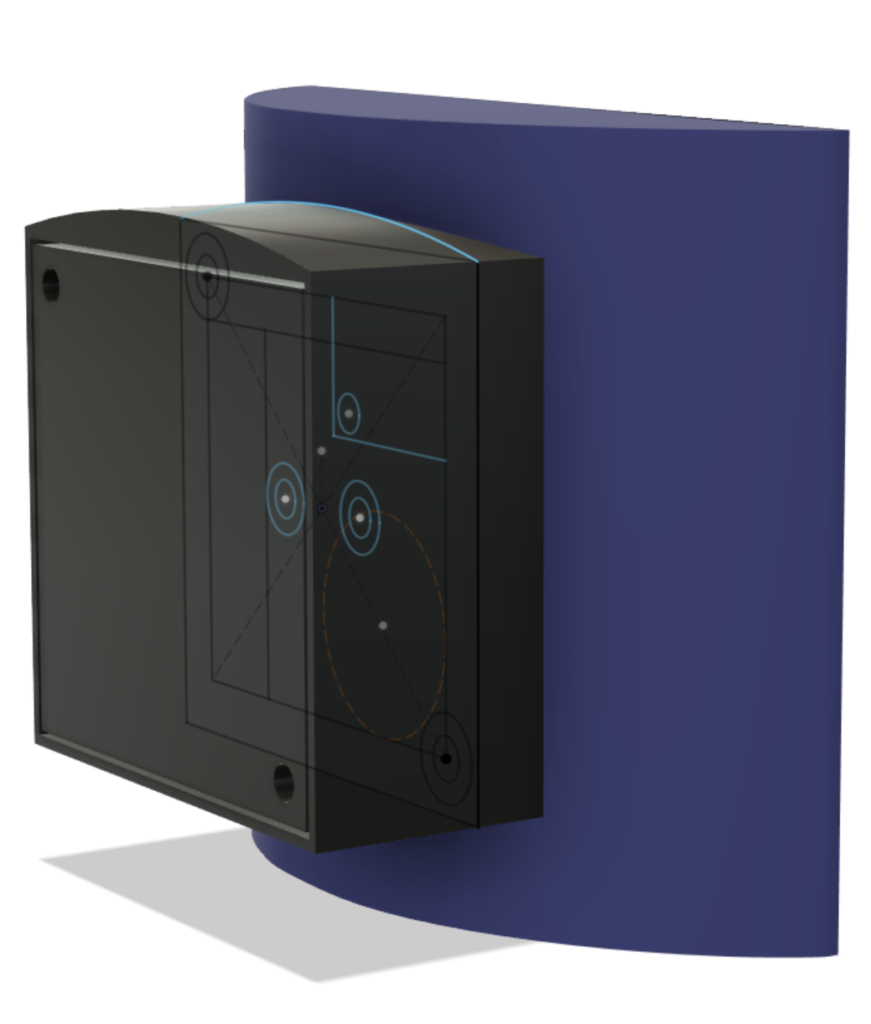
Design for the Back-Pack to Hold the Key Fob On the camera side I also got the 3D printer working to make a case to contain the Pi, camera and 433MHz receiver. This is attached to a sheet metal bracket (made from an old baking tray) which allows the camera to be hung from our windows and the window to still close. I wrote a small Python script that monitors the GPIO connected to the 433MHz receiver and logs any events. It also uses the Motion HTTP API to trigger Motion to record video if the CATWatch is activated.
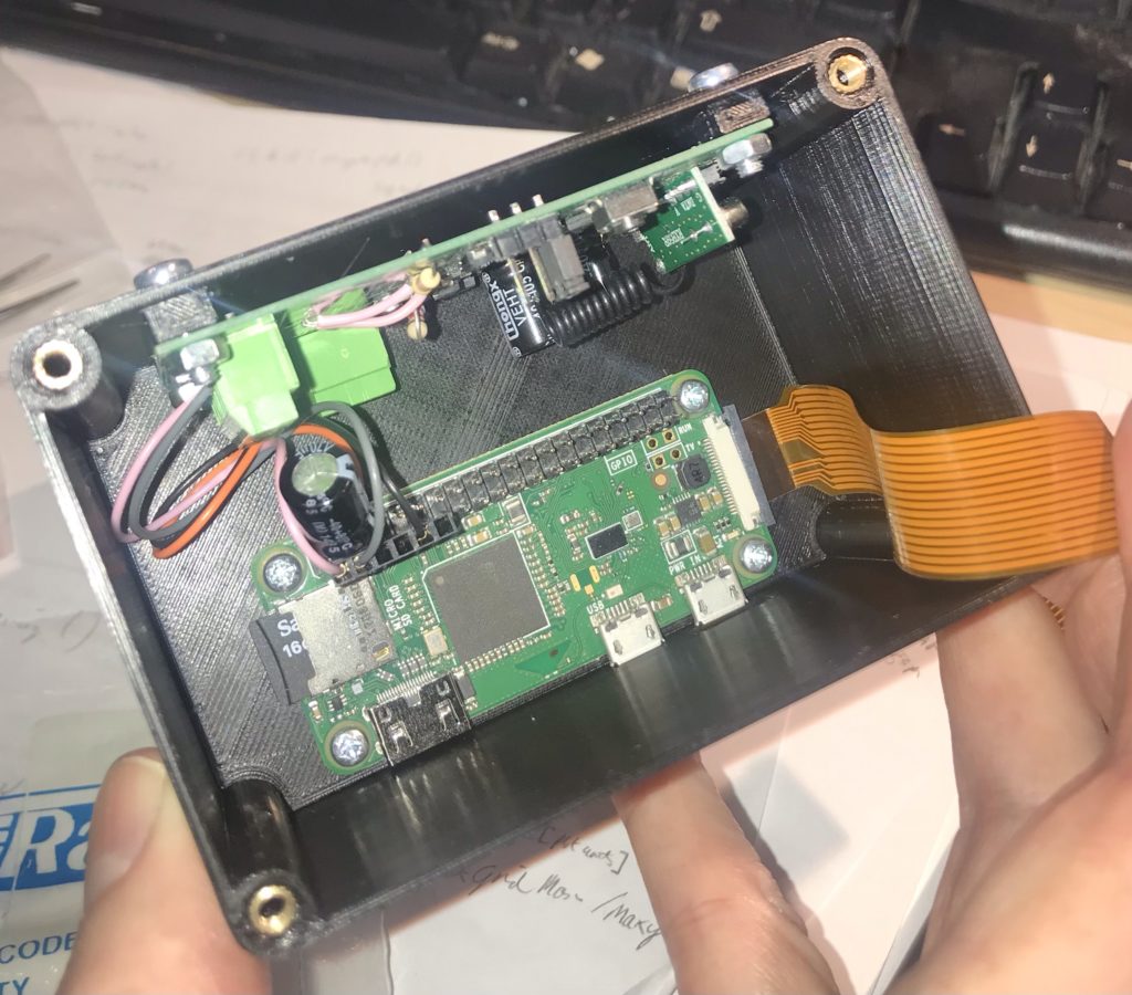
Camera Case – Pi Zero in bottom, Receiver Board on Size, Ribbon Goes to Camera in Lid 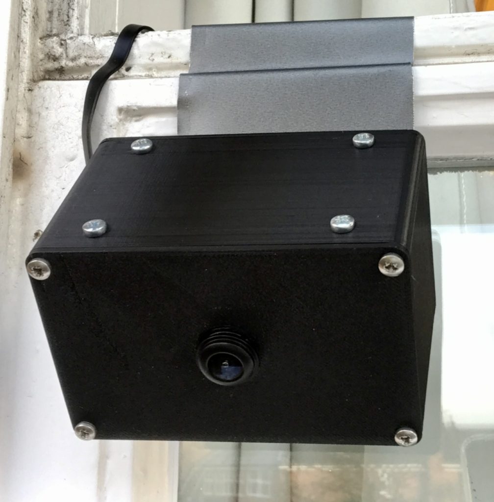
Camera, Pi and Reciver Mounted on Window I am getting about 8 meters line of sight operational range on the 433MHz signal which is good enough for this application. Since it all went live the only animal to trigger the CATWatch was a squirrel which wandered right in front of it. So, touch wood, it seems that the project to secure the garden against TC is working. Come the spring, I hope the nesting birds appreciate the effort. We wait for TC’s next move!
Of course this project is completely and ridiculously overkill, but the new parts were pretty cheap and it was fun to build. It’s nice to do some back to basics local networking and to have a completely self-contained solution that doesn’t depend on some dubious cloud-based subscription like almost all commercial home automation services do. I can see that there are a lot of other potential applications for simple 433MHz technology which I might want to explore.
(1) A couple of notes on the night vision camera. Firstly, the included IR LEDs for night lighting are pretty feeble. They might light about 2-3 meters, but not further than that. I ended up removing them as they weren’t lighting anything useful when the camera was on an upstairs window. They also cause false positives when it rains due to reflection from raindrops.
The IR LED modules are self-contained (including a light sensor to turn them on) so they could possibly be repurposed as a light source to be used away from the camera. Without IR illumination the camera doesn’t really see in the dark, so I would probably have go for a normal (non-IR) camera if doing this again.
The camera comes with a choice of lenses. Due to breaking one camera I ended up with both lens options. One thing to note is that the lens needs to match the plastic base that it screws in to if it is going to focus properly. If you want to swap lenses on a board you can’t just move the lens over, you also need to move the base.
-
The Story of Pye Wireless
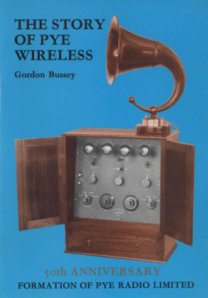
Posted on October 16th, 2018 No commentsBit of an odd one today – while helping my dad clear our some of my old books we found this pamphlet from 1986 – “The Story of Pye Wireless” by Gordon Bussey. I can’t find any other references to it on the web, and it seems well researched with some nice photos. So, to make it more widely available I’ve scanned it and made a copy available.
-
VCV Rack for EMF Camp 2018
Posted on August 28th, 2018 No commentsI am running a beginners workshop on the VCV Rack moduler synthesizer simulator at EMF Camp 2018. Currently scheduled for 11.20 am on Sunday in Workshop 1. If you are at EMF Camp and want to join please bring a laptop and headphones.
Here are some resources for the event:
- VCV Rack Cheat Sheet
- Beginners VCV Rack Workshop slides
- Example VCV Rack patches