

-
Fixing the cutest proper scope – Sincair/Thandar SC110A
Posted on July 31st, 2015 No commentsWhen doing some research on the web about my Philips X.40 electronics teaching kit I found out about the contemporary Philips EE2007 kit which had a battery operated CRT for the teenage nerd to play with. Just how cool is that? Even as an adult I immediately wanted something similar. The schematics of the EE2007 CRT module are easily available and I thought about building a clone using modern components but, to be honest, I am a bit of a scardy -cat when it comes to high voltages and I didn’t fancy getting to grips with the HT supply. Like so many others the project went on the back-burner.
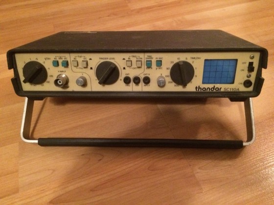
The original eBay photo – looks OK
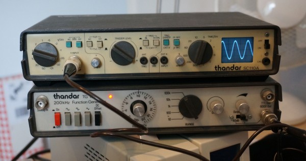
Recently though I was thinking about upgrading my boat-anchor oscilloscope (it’s a 1980s(?) high-spec Hitachi hybrid analogue/sampling scope which is a joy to use but massive and very limited by today’s digital standards) and I thought I might be able to get a second hand modernish digital scope on eBay without spending too much. I didn’t find the ideal match there, but I did see a Thandar SC110A miniature analogue scope. It was love at first sight – a battery powered scope in a small, smart enclosure that matches my function generator which is always on my electronics bench. Some people find kittens cute but, for me, this dolls-house scope with its tiny 4cm diagonal screen just makes me feel all squeeeeeeeeeee. In XY mode I could use it like the EE2007 CRT but with added convenience of calibrated amplifiers and a timebase (no intensity input though).
The scope was described as working but I was always sceptical because eBayers are often economical with the truth and anyway not many people would know how to test it properly. Without being cheap it was at a price that I was prepared to spend for a bit of fun so I bought it expecting I would have to do some remedial work. When I got it there was good news and bad news. Good news was that you could get a “bright line” trace with no signal and most of the functions seemed to do vaguely the right thing. Bad news was that the display had awful distortion and freaky interactions between the X and Y axis. Also some of the input ranges on the Y axis didn’t seem to work. Time for fault-finding and recalibration using the handily supplied service manual.
To do the calibration you turn the scope upside down and take the bottom half of the case off which exposes the main circuit board and calibration controls. Once inside you see that the circuit board is actually branded Sinclair so you will understand if I was suspicious that it could ever be made to work properly at all. In fact Thandar and Sinclair seemed to have cooperated on several test instruments. Sinclair seems to have picked up the case mouldings from Thandar and Thandar sold several Sinclair instruments under their own brand (brave decision). This design seems to have originated in Sinclair and the CRT, as we will see, was custom made for Sinclair for their microvision pocket TVs.
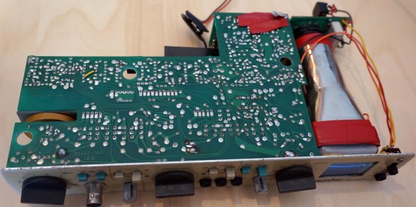
Ready for repair
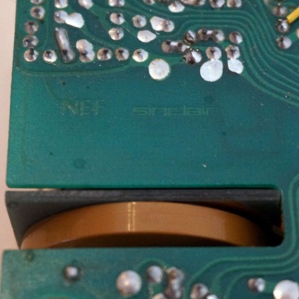
The mark of the devil
When I powered the scope up to calibrate it I realized that it had a fault that I had never seen before in any device. It worked, to an extent, the right way up but when you turned it upside down the trace disappeared and the whole thing seemed dead. I spent a long time turning the machine one way and then the other trying to find out where the thing stopped working and where the fault might me. Eventually I heard a little tinkle that seemed to come from inside the CRT which alerted me to the real cause. Sometimes electronic debugging involves all your senses. Removing the screening foils and looking inside the CRT I found that the glass supports holding one of the Y axis deflection plates and place had broken it the electrode was just flopping around – coming in to contact with other electrodes when the scope was turned upside down. Humm – eBay seller was dodgy on that one IMHO. Still, at least we have a plausible explanation for many of the problems.
Now, where do you get a custom made Sinclair CRT from in 2015? A few specialist shops had them listed at silly prices and were out of stock anyway. Then I had an inspiration – my searches had told me that the Sinclair Microvision TVs used the same tube so perhaps I could get one of those and cannibalize it. Back to eBay and, yes, there was a suitable Micovision for sale at not too high a price.
While waiting for the Microvision to arrive I did the best to fix the other problems working with the dodgy tube. To do this I had to strip the case off completely so I could run it the right way up and still access the controls. As a matter of routine I decided to replace all the polar capacitors (tants and electrolytics) in the design. It has a switching power supply which is nice and compact and gives it a very wide tolerance of supply voltages. In my experience switching power supplies were pretty rare at the time so this might have been a brave design. Normally in test equipment you see a lot of effort going in to conditioning the power supplies with great big capacitors to smooth them. In a sign of classic Sinclair cost-cutting the biggest supply capacitor in this scope is 47uF. It seems to work well enough though.
Next I turned my attention to the dead ranges on the Y Axis. . I spent a long time investigating possible faults with the switch or problems with the Y input buffer. In fact I should have checked the obvious. There is a “DC Offset” trim which needs to be set right to get the input buffer working correctly on all ranges. RTFM applies here.
After a few days my Microvision arrives in the post. I have to say it does look like a proper gadget and must have been quite a cool thing when it was new. As far as I can tell, with no suitable source for a modulated analogue TV signal available, it worked fine. Inside it’s in good condition and there is a surprising amount of space in the case. I feel a bit bad about whipping its tube out and swapping it for the broken one from the scope but I reckon it’s better to have one useful device that works than a TV that is no longer usable in the digital era.

My Sinclair Microvision
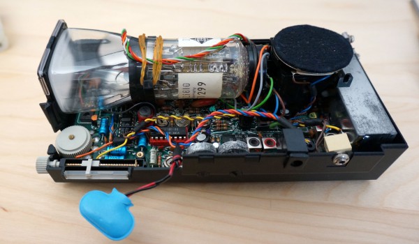
Interior of Sinclair Microvision with the precious tube
With the new tube in and the polar capacitors replaced the scope is working a lot better. Almost everything seems fine except that the Y signal is still very distorted. My fear at this stage is that the shorted electrode in the old tube has damaged some components in the Y amplifier and it’s going to need a lot of debugging and component sourcing to sort it out. In a moment of inspiration I wondered if looking at the lissajous figure from feeding the same signal to X and Y might be useful to understand what was going wrong. Instead of the expected straight line I saw a very definite knee – like some part of the amp was saturating. It turns out that setting up the calibration for the Y amplifier involves two interacting gain controls. The previous person to set this up had set one way too high and the other way too low forcing the amp in to saturation and clipping. Once both had been reset to near their midpoints the amp worked just fine. To be fair the service manual doesn’t explain how to set these controls very well and it requires a bit of electronics experience to know what you are supposed to do.
Aren’t they cute?!
With the Y amplifier recalibrated everything now works very nicely. Technically it’s certainly not a great scope but its simplicity is lovely. The tiny size is very practical. I like the immediacy of analogue scopes. You interact with them much more by intuition rather than digital scopes where you have to think. For answering the eternal electronic engineering question, “do I have a signal here?”, on my audio circuits it will be very handy. As I nice final touch I made a lead so I can use a USB battery booster that I got as a freebe from a trade-show as a power supply. It should run for about 10 hours on a charge. It’s just a really nice thing! I’ll maybe think about whether I can add an external control for the intensity and perhaps do a DIY TV on it.
Updates – 2022 – More History, Notes, Upgrades
I’ve been learning a few new things about this ‘scope recently which are worth saving, and also done some upgrades that I want to mention.
The SC110A CRT isn’t actually a Sinclair product – it was made by Telefunken and has model number D5-100W. In fact, the SC110A isn’t the only scope that used the CRT. Incredibly, a company in California called Non Linear Systems (NLS) made a two channel scope. Given how hard it is to properly see a single channel on that tiny CRT, it must be quite an experience to try and view two at once.
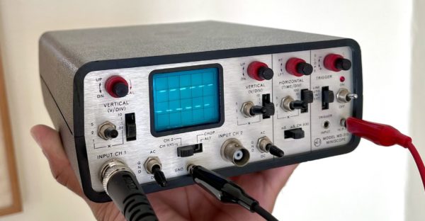
NLS MS-215 Scope – photo from Mohit Bhoite on Twitter An Upgrade for the SC110A (No Soldering Required)
The rotary knobs have a very small molding on one end to show what they are pointing to. These are almost invisible in use, and you can’t tell which end of the pointer you should be looking at. Put something very visible on the active end of the pointer to help read the dials.
Triggering
The trigger control on the SC110A is odd in that it uses different parts of the range for +ve and -ve triggering – normally this is done with a separate switch. On most scopes you would set the trigger control to the centre as a starting point to find the right trigger position. On the SC110A the middle position is actually the transition between +ve and -ve triggering and therefore not actually useful. The equivent to a normal “middle” position would be about 3 o’clock or 9 o’clock depending on whether you want +ve or -ve triggering. So, keep this in mind when trying to dial-in the trigger.
In fact the whole triggering system is rather hard to adjust and not very well scaled. At least on my scope a lot of the range of the trigger control is mostly useless. It looks like the circuit design can have a lot of variability in where the trigger lands, so to accommodate this they put a lot of “slop” in the trigger control.
I build a model of the trigger circuit in circuitjs to understand it better.
Based on the model and measurements on my scope, I’ve changed R4 from 10k to 13k in mine to try and make more of the trigger adjustment range useful.
Calibrated X Input
The manual for the SC110A says the X input is about 0.5V/division, but doesn’t give any calibration process for the input. I was doing some experiments with X-Y mode on the scope and wanted the X input to have a known scale. When I measured my scope the X input was more like 0.4V/dvision. It turns out that there are separate adjustments in the scope for the timebase speed and the X amplifier scale, so it is possible to adjust the X input to a precise value, it’s just that the calibration procedure doesn’t give a process.
I made my own adjustment by first adjusting the X amplifier gain so that the X input was on 0.5V/division, and then adjusting the timebase to run correctly using the process in the service manual.