-
VCV Rack for EMF Camp 2018
Posted on August 28th, 2018 No commentsI am running a beginners workshop on the VCV Rack moduler synthesizer simulator at EMF Camp 2018. Currently scheduled for 11.20 am on Sunday in Workshop 1. If you are at EMF Camp and want to join please bring a laptop and headphones.
Here are some resources for the event:
- VCV Rack Cheat Sheet
- Beginners VCV Rack Workshop slides
- Example VCV Rack patches
-
Everyday Electronics Magazine
Posted on March 17th, 2018 No commentsEveryday Electronics magazine is something I have fond memories of from my childhood. Much of the practical knowledge I have of electronics originated from things I read there or stuff I tried to make (some of it DID work). For many years my parents kept-up a subscription for me until sometime in the late-80s when I outgrew it.
There is quite a lot of info online about EE’s sister publication Practical Electronics (which it would eventually merge with to create Everyday Practical Electronics) but I can’t find a lot written about EE. Recently I saw an edition of EE that recognised as one I originally owned in a second hand shop. At 20p it was an easy decision to take home.
EE always put a bit of effort in to the cover which is one thing that makes them memorable. This one with the dodgy looking vicar and his assistant is perhaps memorable for the wrong reasons. The projects are typical of what I remember – endless variations on simple circuits with oscillators, discreet transistors, 4000-series CMOS and op-amps. Even the cover project isn’t that exciting, though if you were in the market for an electronic wheel of fortune I guess it would do the job. They might have been basic and (whisper) not terribly useful but building them was still a great way to learn practical skills.
The features are quite interesting and remarkably well considered in terms of content. Magazines like EE were the main source of information in the pre-Internet era and you can almost see how the different features mirror popular Internet content today. In “For Your Entertainment” Barry Fox makes some interesting comments on the current state of flat-screen displays before getting side-tracked in to a discussion of Sinclair’s doomed flat CRT project. The government didn’t half invest in some rubbish projects in those days. Some of the features do hint towards the tide of consumer electronics that would spell doom for much of the old hobbyist world. Another glimpse of the future is the side-bar on direct broadcasting by satellite in “Radio World”. The introduction of DBS as a platform for Sky TV was a huge step towards today’s media landscape.

As a child, my favourite regular feature became “Counter Intelligence” by Paul Young. I liked his witty, caustic and grumpy musings on life in the kind of corner electronics shop that was already finding times tough. I remember that dad used to take me to a shop in Leicester staffed by blokes in beige lab-coats stocked with thousands of components in tiny draws. They hardly ever had exactly what you wanted but could usually produce something that would do the job.
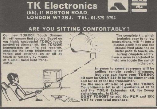
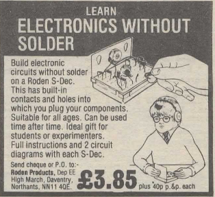
The adverts are a real blast from the past. Many of them seemed to run unmodified for years and years. The spiv zapping his light and the odd boy with his crystal set were almost permanent features. I imagine J Bull (Electrical) always doing deals on vast lots of unwanted items and then finding enticing descriptions to sell them off to the unsuspecting.
So, for anyone who, like me, wants to wallow in nostalgia, or just see what the old days were like here is Everyday Electronics August 1981.

-
The “Electronics Kit” Common Emitter Amp
Posted on August 20th, 2017 No commentsOne project that’s been in my mind for ages is to revisit some of the circuits from my childhood Philips X40 kit. I finally got around to putting “Experiment 5 – Telephone pick-up and amplifier” in to my circuit simulator. This is the first of several audio amplifier circuits in the manual, and they all follow the same design pattern. Similar circuits are also used in other educational kits. I had tried to use this circuit design in my own electronics experiments as a kid. Mostly it didn’t work, but sometimes it did. As an adult, I was interested to understand its characteristics to help explain where it’s appropriate.
View the about in full screen.
Looking at the simulation you will notice the amplifier is non-linear (compare the shape of the top of the sine wave out to the bottom in the output of the first stage). This isn’t unexpected given that transistors have an exponential relationship between the base voltage and the collector current. The biasing on the second stage also looks bad, meaning that the output signal is clipped on the positive side. The simulation result raises several questions in my mind:
- Why is this type of amplifier so popular in basic electronic kits?
- Are they circumstances in which the amplifier is linear?
- What are the characteristics of this type of amplifier anyway?
To answer these questions, let’s look at the basic building block of this amp. It’s a single transistor common emitter configuration. The biasing is from a high value resistor between the collector and the base. Wikipedia informs me that this configuration is called “collector feedback bias“. The signal is coupled in and out of the stage through capacitors.
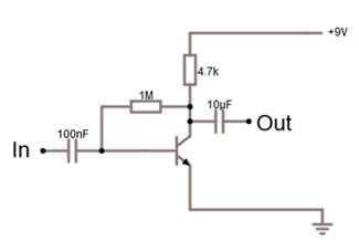
Single Stage of Amplifier
Looking at this circuit you can guess why it’s popular in these kits: the component count is very low. Hence, it is easy for kids to build. If you have an intuitive understanding of transistors, you might also guess that resistor between the collector and the base creates negative feedback giving the circuit the ability to find a suitable operating point across a range of conditions.
As all the textbooks tell you, transistor amplifiers require that the transistor(s) are “biased” correctly to work. The aim of biasing is to set the DC conditions around the transistor so that it is in the “active zone” of operation. The active zone means that you are past the threshold for the base voltage required to start to turn the transistor on, but not yet at the base voltage where the transistor is fully turned on and saturated. The DC conditions that the biasing establishes are called the “operating point”.
As I mentioned, in this circuit the base resistor provides negative feedback which tends to stabilize the operating point. When the circuit is switched on there is no current through the transistor so the collector voltage is at the power supply voltage and the base is pulled high though the two resistors. This rising base voltage turns the transistor on and this pulls the collector voltage down (because of a voltage drop through the collector resistor) which in turn reduces the base voltage – tending to turn the transistor off and reduce the collector current. In practice, these effects will almost instantaneously reach equilibrium with the transistor in a partially on state – i.e. in its active region.
Wikipedia gives a pretty good explanation of how to calculate the operating point so I won’t repeat it. One thing to note though, for the resistor values used in this configuration, the operating point will depend on the gain (β) of the transistor so the operating point will change for different transistors. Here is a graph showing how Vc depends on the gain (β).
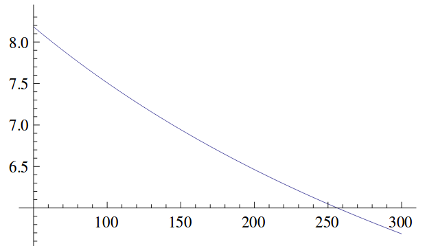
Theoretical Vc (Y axis) Vs Gain (X axis) for Circuit Shown Above
So, that just about wraps-up the situation for the DC bias. It works just about OK as long as you aren’t fussy and don’t expect a big output voltage swing I guess! What about the AC characteristics of this circuit? What is the gain? What about this non-linearity effect?
I checked a few standard text books, and the web, and couldn’t find a theoretical treatment for this circuit configuration so I had to come up with my own. Let’s start by assuming that the impedance of the input source through the coupling resistor is low compared to the input impedance of the amplifier. In that case the input signal becomes just a change in voltage on the base of the transistor (ΔVBE). In that case we can use the Ebers-Moll equation for the transistor to work out the impact on the collector current (and hence the collector voltage). Ebers-Moll says:
IC2/IC1 = Exp( ΔVBE / VT ) Where VT ≈ 25.3mV at room temperature
If you write IC2 = IC1 + ΔIC, and convert the collector current to the corresponding voltage you can get the solution:
ΔVC = ( 1 – Exp( ΔVBE / VT) ) . ( VCC – VC1 )
Where VCC is the power supply voltage and VC1 is the voltage at the collector at the quiescent operating point
That equation fascinates me for two reasons:
- Clearly, this is an exponential amplifier – which explains the non-linearity
- The gain depends on the collector voltage at the quiescent operating point. The graph above which shows how the operating point changes with β translates to changes in the stage gain.
Can we imagine this amp could be approximately linear? Well, as my high-school physics teacher said “everything is linear if you look at a small enough range” (cue sound of 1,000,000 mathematicians groaning). So, we know by Taylor expansion that:
Exp( x ) = 1 + x + x2/2! + x3/3! + …
So, if ΔVBE << VT we can approximate the exponential using just the first two terms above.
ΔVC ≈ – ( ΔVBE ) . ( VCC – VC1 ) / VT
In other words, for very small input signals (<< 25mV) it is kind-of, sort-of, a linear amplifier of gain ( VCC – VC1 ) / VT . Here are some handy plots from Mathics of gain Vs β, Rc and Rb.
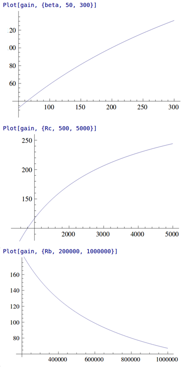
Stage Gain (Y axis) Vs β (Top), Rc (Middle), Rb (Bottom)
Actually, the stage gain in this configuration is quite high, though very dependent on the β of the transistor. I might also remark that the output impedance is poor (limited by Rc ), though, without having done the calculation, I think the input impedance is probably OK.
So, if you want a high gain, single stage, small signal amp with very few components, and, you aren’t too worried about predictability of the gain OR linearity OR output impedance then this circuit just about does the job. This actually fits the bill for these beginner’s electronic kits pretty well. If your requirements are more stringent then better avoid this circuit and look for others. Just one thing still seems odd – why is the second stage bias set where it is on the original circuit?
For me it’s been interesting to look at how much information you can extract about this, fairly trivial, circuit and it’s certainly refreshed my understanding of transistor fundamentals. I hope you find it interesting too.
-
JavaScript Objects – some key examples
Posted on March 28th, 2017 No commentsSome of the JavaScript handling of objects is pretty wacky IMHO. Here is some code that illustrates some key points:
- Global, private and instance variables
- Privileged and private functions
- How “this” is assigned and how to work around that
See also: http://www.crockford.com/javascript/private.html
Some may point out that my application of OOP terminology to JavaScript isn’t correct. Strictly, what I am showing here are properties of the way JavaScript implements closures, but for people coming from an OOP perspective it’s helpful to be able to understand how to achieve some common OOish goals.
// This is a constructor Test function Test() { // Assign the private instance variable "self" to the value of this in the constructor. // More later on why we want to do this var self=this; // Assign a global variable g (probably not what you want to do in a real object!) g="global"; // Assign a private instance variable p var p = "private"; // Assign an instance variable i self.i = "instance"; // Create a private function pp (can't be accessed form outside the object) function pp () { console.log("pp"); } // Another way of assigning a private function var ppp = function () { console.log("ppp"); } // Create a 'privileged' function (public function that can access private info) this.p = function() { pp(); ppp(); console.log("p="+p); console.log("this.i="+this.i); console.log("self.i="+self.i); } } i="global i"; // assign i as a global o1 = new Test(); // o1.pp(); - would be an error - pp is private "o1.pp is not a function" // o1.ppp(); - would be an error - ppp is private. o1.p(); // Outputs 'pp', 'ppp', 'p=private', 'this.i=instance' and 'self.i=instance' console.log("Now with a call-back"); setTimeout(o1.p, 1000); // outputs 'pp', 'ppp', 'p=private', 'this.i=global i' and 'self.i=instance' // What's going on - // In the callback case the "this" is set to the current context which in this case is // the global document - hence getting the global "i" instead of the instance variable "i". // To get the instance variable i we want the value of "this" which was used during the // constructor which is stored in "self". -
Vactrols and replacing variable resistors with control voltages
Posted on August 3rd, 2014 No commentsIn a lot of electronic audio circuits the response is controlled by a variable resistor rather than a control voltage (CV). If you want to adapt these circuits to use in a modular configuration then you often feel it would be nice to replace or augment the variable resistor with a control voltage input. In some cases this can be quite easy – the variable resistor might just be set up as a voltage divider between two DC levels and effectively the output of the wiper is a control voltage. However it is often the case that the variable resistor is actually manipulating a waveform inside the circuit. For example, in a lot of filter designs the resonance level works on a variable resistance controlling the amount of positive feedback from the output to the input and this isn’t easily replaced with a control voltage.
I recently got this question from the web:
I want to add external CV [control voltage] control to an existing circuit. It’s to control the resonance of a filter where there’s already a pot to do this manually. My first idea was to use a vactrol and run the resistance from that in sequence with the pot with the pot then acting as an offset whenever there’s CV applied. However there’s a few things I’m struggling with.
1) It’s always only going to be a positive offset, even if you feed a bipolar signal to the CV, being that the vactrol can’t output negative resistance 🙂
2) What’s the strategy for managing current limits going to the vactrol? I’m familiar with *reducing* current via resistance but what if you don’t actually know what the current is going to be? How do you bring it within a usable range?
3) The big question: is this the best way to achieve the original aim? Any other suggestions?This question nicely captures the classic problems in this situation – there isn’t an easy general purpose way of changing a control voltage in to a variable resistance. The simplest approach, as suggested here, is to use a vactrol. For those not familiar with the term a vactrol is a light pointing at a light dependent resistor in a sealed unit. By connecting the control voltage to the light you generate a variable resistance that depends on the control voltage while keeping the control voltage electrically isolated from the resistance.
Vactrols are easy to use but have lots of limitations – they don’t have a well defined relationship between the CV and the resistance and the range of resistance values achieved may not match what you want in your application. Generally they also have quite slow response. There isn’t much you can do about these limitations. Some kind of preprocessing of the CV might help set the range of resistances achieved to better meet your needs. You will also want to introduce the light dependent resistor in to the circuit with some kind of additional adjustment (perhaps the existing control) to set the control-point it is working around. For example, to get a bipolar response (Q1 above) you can add a DC offset to the CV so that the bipolar signal becomes an alternating positive signal and then set the adjusting resistor to position the range of the output to be that you are interested in. You can try putting the vactrol in series with the adjusting resistor instead of in parallel.
As far as I know most vactrols will go down close to 0 Ohms resistance when the controlling light is fully-on. This gives you the lower bound for the resistance, and hence upper bound for the in-circuit current. As just about all variable resistors also go to 0 Ohms you can pretty much add a vactrol in series or parallel with an existing variable resistor from the point of view of the minimum resistance (Q2). If you don’t want the vactrol to drop to 0 Ohms put a resistor in series with it, or manipulate the CV to limit how large the signal feeding the vactrol’s lamp gets.
As for Q3 – no, sorry there isn’t a general way of replacing resistance-driven circuits with CVs. There are various circuits that are called voltage-to-resistance converters (eg see the LM13700 datasheet) but in reality these have complicated limitations on how they can be used and don’t fully isolate the CV from the rest of the circuit. Unless you know a lot about how the circuit you are modifying works and fully understand the limitations it is hard to retrospectively introduce these in to an existing design that uses a mechanical variable resistor. If you *really* want a solution you could have a servo-motor turning a mechanical variable resistor – I can remember a few hi-fi buff friendly amps that used this approach.
Normally though the best you can do is to experiment with different ways of using a vactrol and learn to love their limitations. Any technical defects are called “character” and in classic audio equipment people pay good money for them!
-
My approach to video circuit bending
Posted on April 11th, 2014 No comments I get asked quite often about how I approach video bending projects, so here are my thoughts. Because I am trained as an electronic engineer my approach is theoretically and technically driven as opposed to the experimental approaches that other people may use. I find this works particularly well with video bending because you need to retain the structure of the video signal if it is going to display properly.
When starting out on a project the first thing I do is to find all the documentation I can about the unit. If I can obtain schematics or service manuals then these can be a great help. For an interesting unit I am happy to buy service manuals if they are not available for free because it saves so much time and hassle. So far it has always been a good investment. If I do get hold of good documentation then examining the circuit will often give me ideas about how things might be modified. Basically I am looking for places where key signals, like the separate RGB colour levels, can be intercepted and modified. There is more discussion on that below.
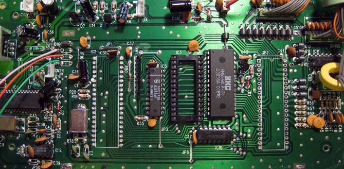
If I don’t have a good manual then I will look at the circuit on the board and try and reverse engineer the key parts. This normally starts with identifying the main chips on the board and through the datasheets and knowledge of the normal operation working out how the signal flows through the circuit. Once you get an idea of the signal flow then you can start to focus in on areas that seem to offer the possibility of modification.
Bending Opportunities
Finding bending opportunities is partly science, partly art and partly gut instinct. You want to find a signal or processing function in the circuit that is amenable to modification. A composite video signal consists of the video information (luminance and colour) combined with synchronization information (horizontal and vertical). In most cases you don’t want to over-distort the synchronization information because this will prevent the signal displaying. Finding opportunities to just modify the video information is important.
For the video signals then a lot of units will separate video and sync information internally. If you can pull out pure luminance, hue or RGB signals from the circuit then you can make these available to process and distort through other circuits without damaging the synchronization. Just additively mixing in audio or other video signals on top of a video signal can be interesting. Some, cheaper, circuits don’t separate the video and sync information and it can be hard to bend the signals for these.
Many video mixers also contain various gate signals that control how different parts of the same picture are processed in different ways. These are used to implement things like wipes and colour fills. Pulling out these gate signals or being able to inject new gate signals can create fantastic effects. Try xoring two gates from different mixers together and then injecting the result back in to the original circuit.
As well as going after the signals you can go after the processing functions. A simple trick is to modify the circuit to remove the limits on how strongly a processing function affects a signal. For example if you have a circuit that controls the colour saturation then it might be possible to boost the gain of this beyond what is intended and create super-saturated and unstable colours in the output.
Another thing I like to do is to see if it is possible to replace manual controls with control voltages. In this way you can sweep control values rapidly, even within one frame of a video, under the control of an external circuit. A lot of effects just come from feeding an audio signal in to a control voltage that varies some aspect of a video signal.
Intellectually I find it more interesting and more satisfying to work with primarily analogue video equipment, but I guess I should add a word on digital equipment. In circuit bending on digital circuits a common technique is just to ground certain address or data signals so that the circuit starts to misbehave. The results are unpredictable, but fun. This approach carries quite a high risk that the outputs of the digital circuits will be damaged as they try and drive a grounded signal “high”. I suspect this is the cause of a lot of equipment damage caused by circuit bending attempts. One reason you can get away with it on some older equipment is that they used NMOS logic. A feature of NMOS is that it has no active pull-up device (just a resistor) so grounding the output is acceptable.
Equipment Safety
People often ask me if I have ever blown anything up while circuit bending. So far the answer is “no”. I think this is largely because I am normally working with a reasonably good idea of how the circuit is meant to operate and I understand what common electronic circuits will and won’t tolerate being done to them. However, circuit bending is a full contact sport. If you can’t tolerate the risk of destroying what you are trying to bend then you shouldn’t have opened the case.
Personal Safety
Personal safety is your responsibility. My very strong preference is to only work on equipment that is powered from a low voltage source or, if it has an internal power supply, where the high voltage elements are fully protected against accidental contact. I recommend you don’t work on designs where high voltage components might be touched.
Older equipment will contain lead, and possibly other unpleasant chemicals. Always take appropriate precautions including through hand-washing before handling food.
I don’t know how much it is possible to teach circuit bending. Particularly with video it is a black-art and relies heavily on experience and luck. Hopefully these hints will help those that want to give it a go though. With a lot of old analogue equipment being sold cheap just get something and start exploring.
-
Equation for op-amp sum/difference amps
Posted on June 2nd, 2013 No commentsWarning: this post contains maths
I can never find on the web or in my text books the general equations for op-amps used as combined multi-input summing and difference amplifiers (ie they have several positive and negative inputs). It makes designing mixers for synthesizers annoyingly awkward as I have to rederive the equations each time. So, to save myself having to work everything out from scratch again, here are my derivations and notes on multi-input Op-Amp circuits. I will also take the opportunity to point out some interesting parts of the results.
Main Results
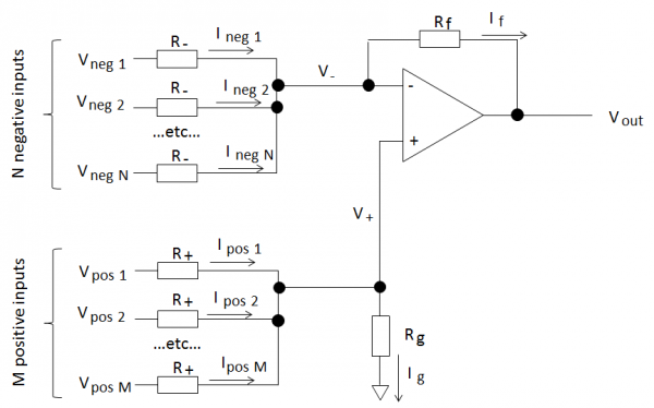
So, here’s the setup:
We have an op-amp circuit with “N” negative inputs and “M” positive inputs as shown above. All the positive and negative inputs are identical.
For an ideal op-amp the output is:
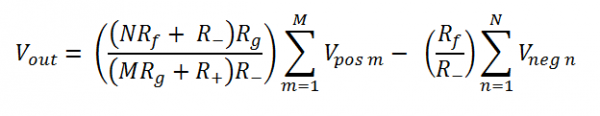
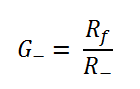
Or, in other words the negative gain is:
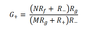
The positive gain is:
Positive and negative gain
The negative gain is nice and easy and only depends on the input and feedback resistors and not on any other variables, like the number of inputs. Why is this? Well the inverting input of the op-amp is a virtual ground and the voltage isn’t changed by the negative inputs. Therefore the current through each negative input only depends on its input voltage. You can have as many or as few negative inputs as you like and it works the same.
The positive inputs are not in this lucky position! Voltages at the positive inputs change the voltage at both the inverting and non-inverting inputs of the op-amp. The non-inverting input voltage changes because of the voltage drop over Rg. The inverting input voltage changes due to the feedback action of the op-amp keeping the input voltages ideally identical. This means that currents flowing through all the input branches depend on the positive input voltages and hence the complicated positive gain equation.
Limits on positive gain values
Once the negative gain is set, this configuration limits the range of values of the positive gain depending on the number of positive and negative inputs. One particular example:
If the negative gain G- > 1 and number of negative inputs N < M, the number of positive inputs then G+ < G-.To derive this then consider that the maximum positive gain is when the input resistors R+ = 0 (obvious from the circuit and also by inspection of the equation).
Special cases and derivation
There are several interesting special cases from these equations (including the basic op-amp single input amplifiers) and the derivation is worth reading. So I don’t fill the blog with equations you can read it all in this pdf file.
-
Dorklake11 – Vibrati Punk Console workshops ahoy!
Posted on August 22nd, 2011 No commentsDorklake11 was a nice event. Great job by Alex, Greenman and co. to create organization seemingly out of nothing. We had 12 Vibrati Punk Consoles built in two workshops
Mike Challis did a very nice build of the Vibrati Punk Console as a Coffee Can Synth.
Sam Freeman made some great phat sounds by looping the Vibrati Punk Console through a Korg Monotron.
Thanks to all the builders and all the campers that put-up with the massed bleeping!
-
Vibrati Punk Console – First Chance to Build
Posted on June 2nd, 2011 No comments
Retro Electronic Sound
Evening Build Workshop
Tue June 14th, 6:30pm, Nottingham Hackspace
All welcomeThe first batch of kits for the Vibrati Punk Console (aka “Atari Punk Console 2.0”) are in. We are going to have a building session at Nottinghack on June 14th. So if you like electronic music or want to try your hand at soldering then come along.
The Vibrati Punk Console is a beginner-friendly electronic music project that can be finished in one evening. The simple circuit generates an amazing range of retro warbles, screams, glitches, fuzzes and tone ramps.
Workshop Cost: £20 includes teaching and all build materials.

For those that can’t make it to Nottingham the kit should be available to buy on the web soon.
-
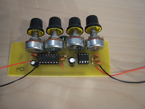
First Home Made PCB
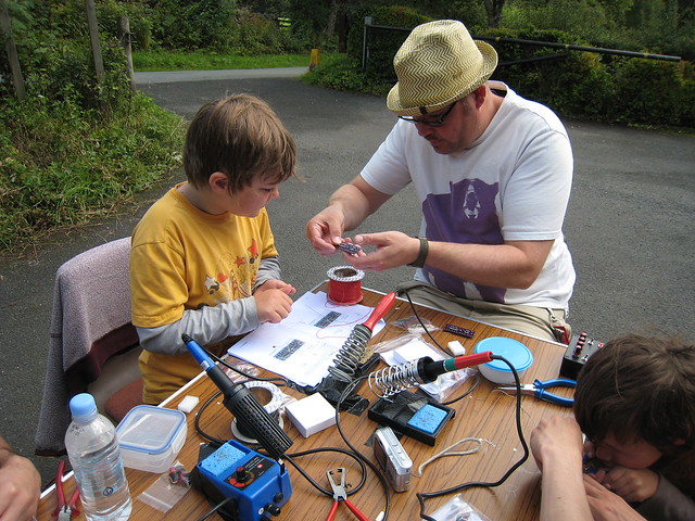
Posted on April 22nd, 2011 No commentsFor most of my projects I either need quite dense PCBs that I get professionally made or I use point to point wiring techniques. At the moment though I am working on a new electronics kit under the working title of “Vibrati Punk Console” which is kind-of an “Atari Punk Console 2.0”. To validate the PCB design before sending the first batch for manufacture I decided to make a home made board.
With great timing Matt Little had just done a PCB workshop at Nottingham Hackspace so I had good practical experience. Armed with a UV exposure box from the last DDRC Car Boot Sale and a set of parts from Rapid Electronics I went out to make my PCB.
I basically followed the tips from Mike Harrison’s guide. For etching I used the Seno GS etching system which manages to keep 99.999% of the really nasty stuff in a bag.
I was delighted that attempt number 1 yielded an almost perfect result.
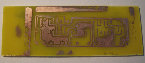
I made a second board as a backup, but that was a complete disaster. Once I developed the UV board you could see that the fine lines weren’t sharp and once I started etching they disappeared all together. Still not 100% sure what the problem was there. Possibly over-exposure to the UV or the mask not being completely flush to the board when it was exposed. Anyway one board was enough so as it was getting late I stopped there.
One thing I would note for future builds – the “automatic” pad size in Eagle is too small for home made boards. Use larger pads than the eagle defaults to make your life easier.
With the board drilled and everything mounted I am delighted to say it worked first time.