

-
My Old BBC Micro
Posted on August 24th, 2022 No commentsAfter a trip “down south” I recovered by old BBC from the loft recently.
It started life as a Model A and was then upgraded to a B, and later a disk interface was added. It also has a big “Sidewise” ROM/RAM board fitted. (My dad was an IT manager for British Gas and was a big believer in upgradability. He approached buying and owning a home computer with about the same attitude as procuring a mainframe for BG. To be totally fair, that strategy did work very well. We got a huge amount of use out of the Beeb over many years.).
Anyway, it’s somewhat dirty but the plastics are in good condition. It’s quite an early board with plenty of factory bodges – the most exciting of which is a variable capacitor trimmer on a bit of veroboard randomly above an IC. The original OS was 0.1, but it was upgraded to 1.2 when that came out.
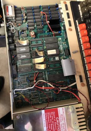
After replacing the usual suspects in the PSU and reseating the expansion board (a problem I remember back in the day) it came straight back to life. Looking at the bodges it’s surprising it worked at all, never mind after all this time. The Cub is a recent purchase BTW, back in the day we had a Philips portable TV with RGB input on the back.
Quite a few ROMs in it – some even legitimate (ISO Pascal, Wordwise). I don’t remember how Basic got upgraded to Basic 2. The more unusual ROMs uinclude PHX (Phoenix) which was a special terminal emulator used by Cambridge Uni and a few others in the UK. It implemented a page editing protocol. I have an odd personal connection to that as I ended up making the official port of the protocol to the Mac 68k era. SSMP is some other kind of terminal emulator (not the messaging protocol), but I don’t remember what I used that for.
Disks and disk drive are currently MIA – possibly still at my dads.
-
Metronome from an Event Badge
Posted on May 3rd, 2021 No comments
Did I mention that I am learning to play the piano? When I started reading music I expected the hard part will be recognising the notes, but with practice I’ve got that fairly sorted. The consistently hard part is recognising the rhythms and being able to play them right. I found having a metronome or drum track really helps with rhythm practice.
I’ve been a bit frustrated that none of the metronome options I found were quite what I wanted. There are 1001 apps of course, offering many features, but I find them a bit painful to configure how I want, and the UIs often trade gloss for practicality. Plus, somehow having my phone in front of me when I am playing isn’t quite nice. Stand-alone metronomes on the other hand seem to be too basic with klunky controls and poor displays. I wanted something that covered 90% of my use cases in a way that was simple, visual and usable.
I also had an unusual requirement that doesn’t seem to be supported in any off-the-shelf solution I could find. I wanted to use a pedal to play the beat myself, but have that mapped on to a drum pattern to help follow the strong and weak beats in a bar.
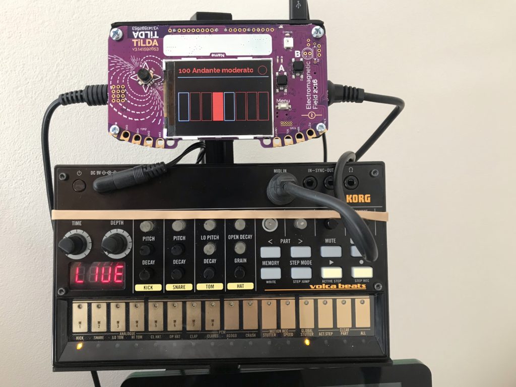
I recently got a Korg Volca Beats (VB) as a way to create easy drum tracks. It’s basic, but fun. It almost passes muster as a metronome too, but again it can be a bit too much effort to configure. My initial goal was to use the sync in signal on the VB to provide a pedal input to step through its sequence. Sounds simple, but in practice it was a nightmare. The VB seems to do some kind of interpolation of the sync in signal and if its slightly irregular it can trigger weird double steps on the sequencer. After a lot of frustration I gave up on that approach.
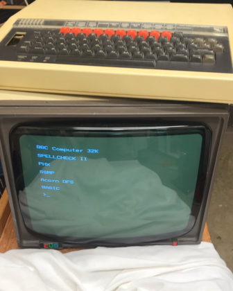
I went for one last try with an idea to use the MIDI in on the VB to trigger the drums from an external sequencer that could work like a normal metronome or be stepped using a pedal. Like many people I have a box full of development boards from various sources and rather than buy something new I wanted to use one of those. It came down to a ESP8622 board from a Nottingham Hackspace event or the Tilda Badge Mk 3 from EMF Camp 2016. Something had broken compatibility between the current Arduino IDE and the ESP8266 board I had, so I went with the Tilda Badge which turned out to be really well suited to the job.
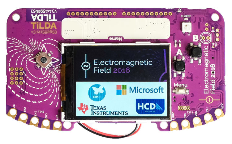
The Tilda Badge Mk 3 The Tilda Badge is programed in Micro Python which is really productive once you get your head round how to use it. The approach I used was different from the ones suggested in the documentation. I connected the badge to my PC which allows it to mount as a mass storage device and as a serial console. Copying a file called “main.py” to the root of the mass storage device creates an application that the Tilda Badge will run on boot. I edited my main.py on the PC and just used a CMD command line to do the copy. To run without resetting the badge, I used this command in the – 115200 BAUD – serial console (courtesy of Stackoverflow):
>>>
exec(open("main.py").read())The advantage of this approach was I didn’t need to install anything special on the PC and I could quickly iterate versions.
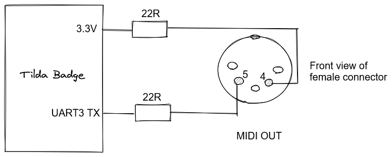
To support a MIDI output I just had to add the simple circuit below to the UART3 TX which is available on the GPIO port of the Tilda Badge. (Note – the pin positions on the DIN connectors used for MIDI are totally confusing. I think this is right, but I would rely on the pin numbers more than the positions in the event of conflict!) The pedal is just connected between the CH1 GPIO pin and ground.
The Tilda Badge turns out to have just the right level of functionality for this application. The connectivity is more than good enough. The display is big and clear enough to show a good visualisation. There are enough buttons to provide easy access to all the services without having to do any “menu diving”.
Software for the Tilda Badge is here (it’s very rough, but does the job).
The finished project integrates in to an accessory system I build with V-slot on the back of my piano stand (that’s another story). I 3D printed a case that attaches the Tilda Badge to the V-slot. It keeps the front of the Tilda Badge PCB fully visible so you can still see its origin, but it protects the back and provides mounting points for the MIDI and pedal sockets.
Overall it is a really pleasing project and it’s nice to find a long-term use for one event badge. It’s fair to say I haven’t been a fan of the trend for electronic event badges – I think a lot quickly become e-waste and they can be a distraction from other parts of the event. But in this case it has been practical as well as cool. It also shows the value of an open, and documented, project that I was still able to pick up the badge after 5 years and immediately start developing on it.
-
BBC Micro on MISTer
Posted on January 24th, 2021 No commentsDuring Covid-19 lockdown one of the things I wanted to do was to revisit some of the old computers I used. I don’t really have the space or inclination so collect the original hardware, so I decided to try out what emulation options exist now.
I have been interested in trying some ASIC based projects, so a natural choice seemed to me to use the MISTer platform. This is a retro computer, console and arcade emulation system based on the DE-10 Nano FPGA development board. This MISTer project was developed from the earlier MIST project which used an older development board.
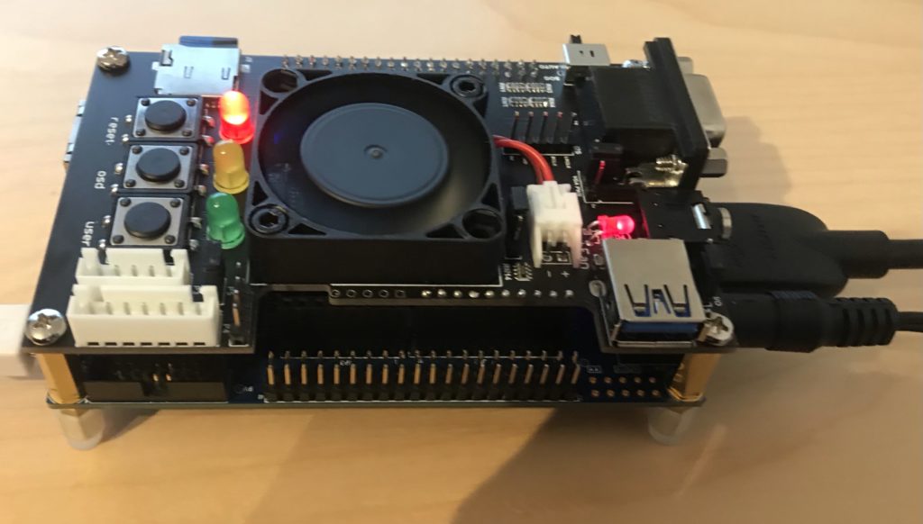
DE-10 Nano with MISTer expansion to support secondary SD Card To get started with MISTer you just need the DE-10 Nano board, but I also chose to get the MISTer add-on board, mostly for the secondary SD Card (more on that later). Most of the emulation cores, but not the BBC Micro, need a RAM add-on board too.
Once you have the DE10 you can just flash the MISTer core on to an SD Card and boot it. You will also need a USB keyboard connected to the “USB to go” socket.
Some useful keys:
CTRL-F11   Break (BBC Micro)
F12        Load MISTer menu
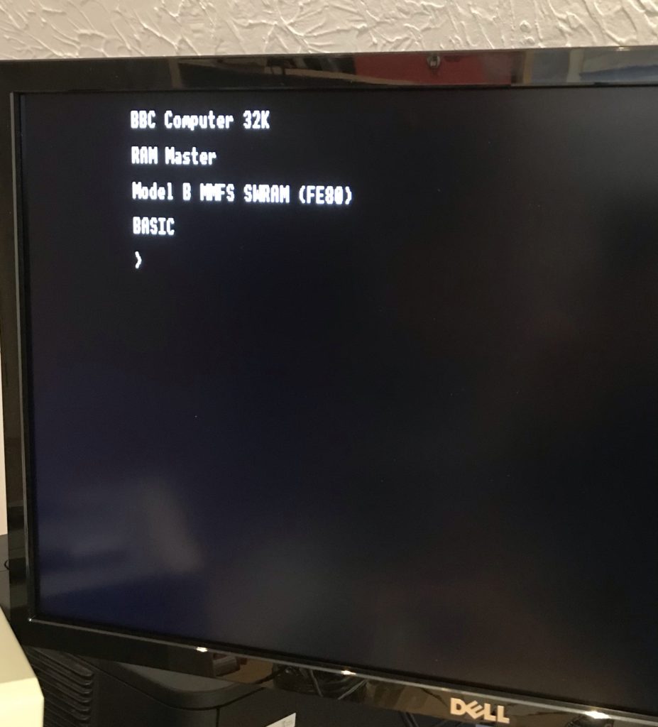
BBC Micro booted using MISTer One limitation of the current core is that it doesn’t support split-mode games like Elite and Revs.
Using BEEB.MMD
The BBC Micro core uses files in “MMB” format. This was a format originally developed for a BBC Micro add-on that connects SD cards to the user port and makes it look like a virtual set of disk-drive. The MMB file is a bundle of hundreds of BBC floppy disk images. Using commands on the BBC Micro you can choose to mount the images from the file in to virtual drives.
The BBC core offers two ways to mount the MMB file. If you have a secondary SD card then format as FAT32 or FAT16. Copy the MMB file as “BEEB.MMB” on to the card. The core will automatically pick up that card. In this mode the file can be both read and written.
The alternative is to rename the file as “.VHD” and copy it to the “games/BBC Micro” directory on the main SD Card. If it is called “boot.vhd” then it will be automatically loaded. If not then you can manually load from the MISTer menu. In this mode the file is read only. To unmount a previously mounted VHD (e.g. to go back to the secondary card) press backspace when picking the VHD.
There are various utilities to manipulate MMB files on PCs. I used “MMBReader” which is available on the stardot forum. On the emulated BBC Micro the MMB file is accessible using MMFS. Note that if no MMB file is available then MMFS will stall the boot of the BBC Micro by displaying the message “CARD?”.
Some useful MMFS Commands:
 *DCAT [start #] [end #]   - List disks in the MMB file
 *DIN [Drive #] <Disk #>   - Mount disk in the specified drive (default 0)
Most of the MMB files you will find on the web are pre-loaded with many original games. By default they boot in to a menu to pick the games. You can disable the autoboot on the first disk by using the command
*OPT 4,0. If you subsequently want to run the boot use*EXEC !BOOT. -
Grid Runner – BBC Micro Juvenilia
Posted on January 20th, 2021 No commentsMy first computer was a BBC Micro Model A (early version with the linear PSU and bodge wires on the circuit board). Later we upgraded it to a Model B. I loved it, and even took it on holiday a few times (!) My parents must have been very understanding.
I was amazed today to discover that the BBC Micro community has saved two very obscure games I wrote in my teens and you can now play them in the browser:
Grid Runner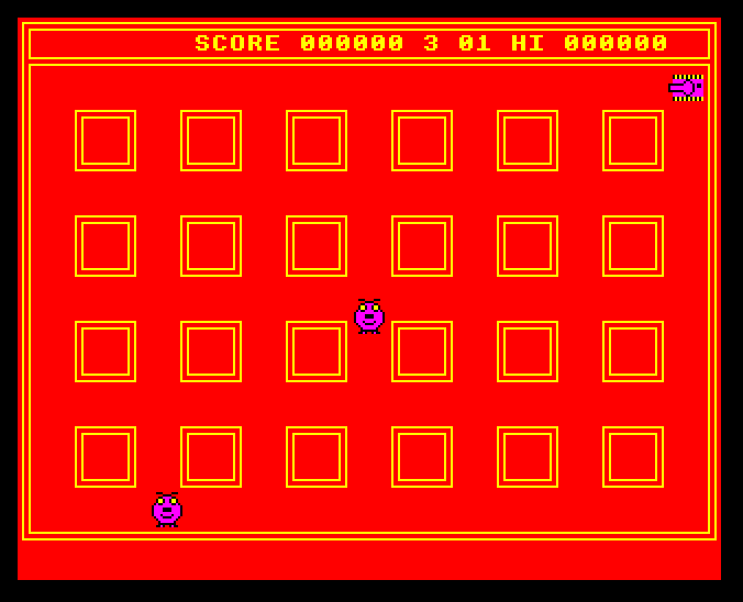
http://www.bbcmicro.co.uk/game.php?id=636
Grid Runner II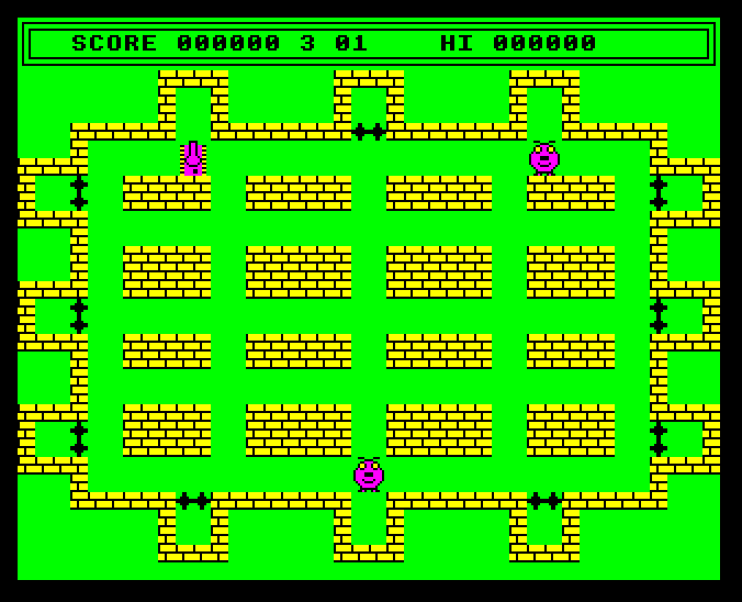
http://www.bbcmicro.co.uk/game.php?id=765
IIRC selling Grid Runner was the first money I ever earned. The BBC Micro magazine Beebug (which was based close to where we live) included it in a demo disk (image via a kind user of the StarDot forums).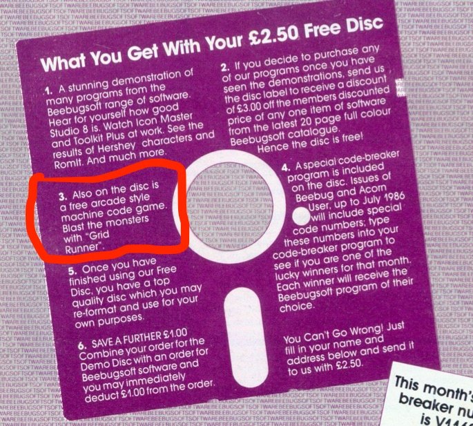
In case you are wondering, I am not colour-blind. The clashing colours were inspired by the BBC classic game Frak.
JS Beeb is fantastic BTW.
-
Networking CATWatch
Posted on December 30th, 2020 No comments(or an overkill solution to tracking the movements of a cat)
I don’t mind cats, but we have one Top Cat (subsequently TC) living locally who thinks he (or she) is the boss of everything. After one too many cat shits and dead birds in our back garden I decided that TC was no longer welcome and was going to be excluded.
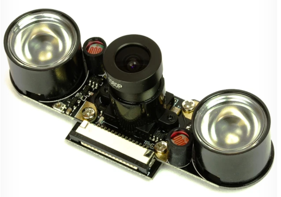
Early steps were very simple – filling in the gap under the gate prevented easy access until TC found new ways over the gate and fences. I then decided a more through approach was needed. I installed a Pi Zero W with a night vision camera module (1) running motion project software so I could see whether TC was coming in the garden and perhaps how it was getting in. It works OK with the caveat that the Motion Project software is pretty simplistic in its approach to doing movement detection and even after tuning the parameters I get a lot of false positives. It is a little painful to manually check the output, but that’s OK.
Night Vision Camera Module (before I removed the IR LEDs) I also put in an ultrasonic cat deterrent on the edge of the lawn. This is a passive infra-red (PIR) motion detector linked to an ultrasonic sounder that is supposed to scare cats. There are lots for sale – I used the RSPB CATWatch. It is a battery powered device where motion detected by the PIR triggers an ultrasonic alarm that sounds at about 20kHz for a few seconds. Interestingly, the alarm doesn’t just play a single tone, it varies the tones during the alarm period, presumably to prevent cats getting habituated to the sound.

RSPB CATWatch After that we didn’t see TC in the garden for quite a while. We thought the CATWatch probably was scaring it off, though we never caught it in the act. But, one day the camera caught TC strolling around the edge of the lawn, just out of range of the CATWatch PIR detector. Knowing TC was still coming in the garden I followed the example of my neighbour and put cat deterrent spikes around the fence tops, and (so far) we haven’t seen TC again.
But, here is the problem, how do I know TC isn’t coming in any more? The camera sees a lot, but it also misses a lot. Despite its name, the CATWatch doesn’t really watch cats, it just scares them off. In fact you have no way of knowing how often it has been triggered. I wanted a CATWatch extension to log when it was triggering, and ideally to trigger the camera to record too. So, there are two problems:
- How to cause a trigger for the CATWatch to activate an external circuit, and
- How to connect the CATWatch to the Pi Zero without running wires everywhere?
I started thinking about how I could get a wireless signal from the CATWatch to the Pi. My requirements were:
- Simplicity
- Keep the CATWatch battery powered without significant reduction in battery life
- Fast reaction so that the camera will be activated while the cat is still in the vicinity.
The obvious option was WiFi, but keeping that running long-term on a battery is problematic. If you disconnect from the WiFi to save power then reconnecting will add a delay which might not meet the “fast reaction” requirement.
BLE was another option, but the thought of working out the right stack of hardware, libraries, low power modes etc. to make it work made my eye twitch. Modern systems are amazing, but, unless you already know the ecosystem and tools, understanding enough to use it effectively can be a massive PIA.
I realised what I wanted was something very simple, almost primitive, that I could just hook up at each end to send an on/off binary signal. The technology that seemed to fit that best was 433MHz radio remote controls used for garage doors and similar things. I bought a set of 5 key fob transmitters and a 2 channel relay board receiver on ebay. The plan was to put a transistor across one button on the transmitter to send and to remove the relay to get an open collector transistor output on the receiver.
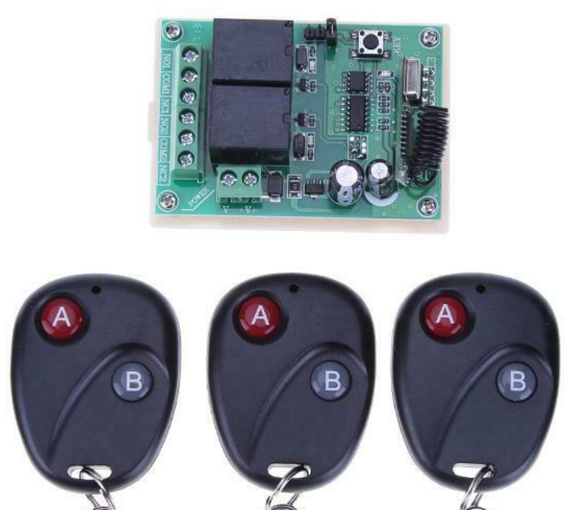
433MHz Receiver Board and Some of the Key Fob Transmitters The receiver board is rated for 12V input, though it worked down to 9V. What I really wanted was for it to be powered off 5V from the Pi. Looking more closely I found, as I expected, that the only part of the circuit that used the 12V was the relay coil. The rest ran on 5V from an internal regulator. I removed the relay and bypassed the power regulation on the board to produce a 433MHz receiver that ran on 5V and could (using an open collector output that originally drove the relay) link to a 3.3V GPIO input on the Pi.
The transmitter fob was very simple – the two buttons just connect a wire to the positive end of the 12V internal battery when pressed. So the only unexpected problem is that I would need to implement a high side switch, rather than a low side switch as I was expecting.
Getting the CATWatch to activate an external circuit would probably be easy, but for one problem: all the electronics are potted in resin except for the power-in and the wires going to the ultrasonic transducer. So, there is no obvious binary “alarm” signal accessible to drive an external circuit. You could trigger based on the ultrasonic output, but I thought it would be easier to use the power input and detect the very marked increase in power consumption that occurs when the alarm is turned on. I put a 15 Ohm shunt in the power line driving a PNP transistor to do the high-side switching for the transmitter (as shown in this simulation). I decided to keep the two circuits on their original batteries, so, to do the high-side switching, these two batteries connected positive to positive as shown.
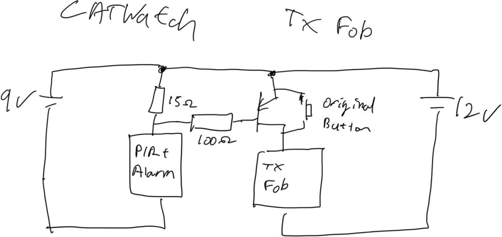
Block Diagram of Connecting CATWatch to the Key Fob Transmitter As always, I hit a snag at the last moment. There was enough space in the CATWatch to include the transmitter fob in the unmodified case, but I found that when the case was closed the alarm wouldn’t turn-off once it had been activated. My suspicion is that the transmitter interferes with some high-Z input that is being driven by the PIR and the circuit keeps thinking it is detecting new motion. So, I 3D printed a “back-pack” that contains the fob circuit and can be attached to the back of the CATWatch away from its electronics. That worked fine and also makes it easier to change the fob battery if needed.
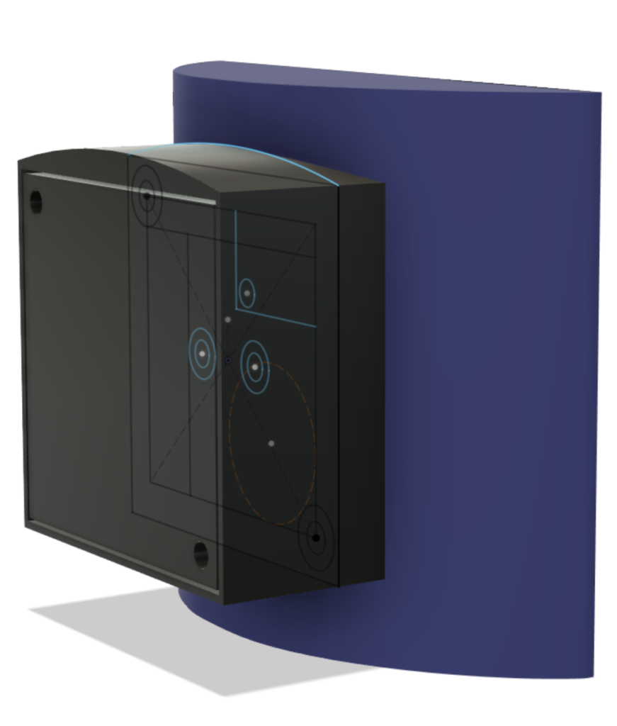
Design for the Back-Pack to Hold the Key Fob On the camera side I also got the 3D printer working to make a case to contain the Pi, camera and 433MHz receiver. This is attached to a sheet metal bracket (made from an old baking tray) which allows the camera to be hung from our windows and the window to still close. I wrote a small Python script that monitors the GPIO connected to the 433MHz receiver and logs any events. It also uses the Motion HTTP API to trigger Motion to record video if the CATWatch is activated.
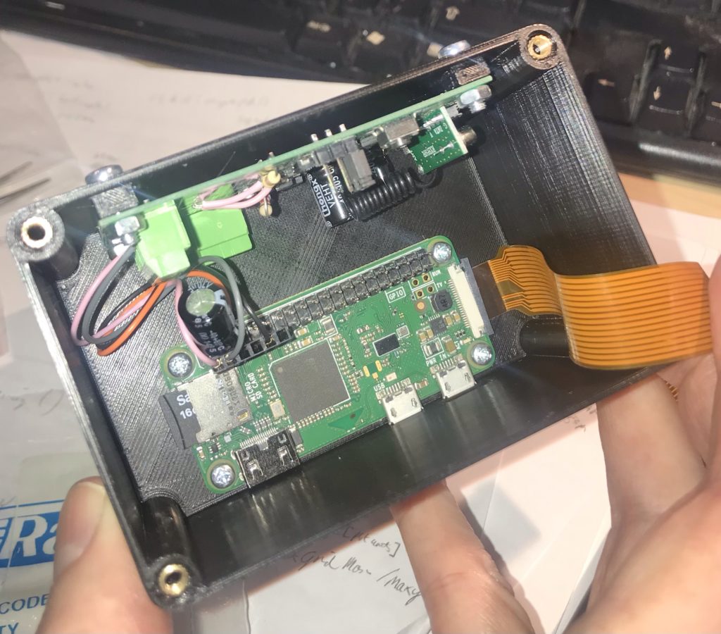
Camera Case – Pi Zero in bottom, Receiver Board on Size, Ribbon Goes to Camera in Lid 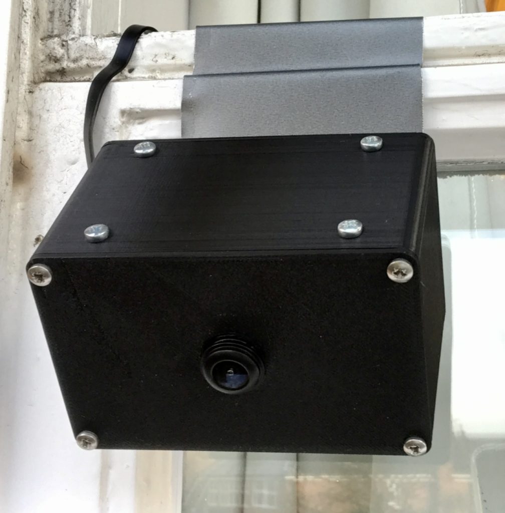
Camera, Pi and Reciver Mounted on Window I am getting about 8 meters line of sight operational range on the 433MHz signal which is good enough for this application. Since it all went live the only animal to trigger the CATWatch was a squirrel which wandered right in front of it. So, touch wood, it seems that the project to secure the garden against TC is working. Come the spring, I hope the nesting birds appreciate the effort. We wait for TC’s next move!
Of course this project is completely and ridiculously overkill, but the new parts were pretty cheap and it was fun to build. It’s nice to do some back to basics local networking and to have a completely self-contained solution that doesn’t depend on some dubious cloud-based subscription like almost all commercial home automation services do. I can see that there are a lot of other potential applications for simple 433MHz technology which I might want to explore.
(1) A couple of notes on the night vision camera. Firstly, the included IR LEDs for night lighting are pretty feeble. They might light about 2-3 meters, but not further than that. I ended up removing them as they weren’t lighting anything useful when the camera was on an upstairs window. They also cause false positives when it rains due to reflection from raindrops.
The IR LED modules are self-contained (including a light sensor to turn them on) so they could possibly be repurposed as a light source to be used away from the camera. Without IR illumination the camera doesn’t really see in the dark, so I would probably have go for a normal (non-IR) camera if doing this again.
The camera comes with a choice of lenses. Due to breaking one camera I ended up with both lens options. One thing to note is that the lens needs to match the plastic base that it screws in to if it is going to focus properly. If you want to swap lenses on a board you can’t just move the lens over, you also need to move the base.
-
Everyday Electronics Magazine
Posted on March 17th, 2018 No commentsEveryday Electronics magazine is something I have fond memories of from my childhood. Much of the practical knowledge I have of electronics originated from things I read there or stuff I tried to make (some of it DID work). For many years my parents kept-up a subscription for me until sometime in the late-80s when I outgrew it.
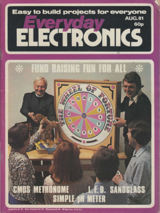
There is quite a lot of info online about EE’s sister publication Practical Electronics (which it would eventually merge with to create Everyday Practical Electronics) but I can’t find a lot written about EE. Recently I saw an edition of EE that recognised as one I originally owned in a second hand shop. At 20p it was an easy decision to take home.
EE always put a bit of effort in to the cover which is one thing that makes them memorable. This one with the dodgy looking vicar and his assistant is perhaps memorable for the wrong reasons. The projects are typical of what I remember – endless variations on simple circuits with oscillators, discreet transistors, 4000-series CMOS and op-amps. Even the cover project isn’t that exciting, though if you were in the market for an electronic wheel of fortune I guess it would do the job. They might have been basic and (whisper) not terribly useful but building them was still a great way to learn practical skills.
The features are quite interesting and remarkably well considered in terms of content. Magazines like EE were the main source of information in the pre-Internet era and you can almost see how the different features mirror popular Internet content today. In “For Your Entertainment” Barry Fox makes some interesting comments on the current state of flat-screen displays before getting side-tracked in to a discussion of Sinclair’s doomed flat CRT project. The government didn’t half invest in some rubbish projects in those days. Some of the features do hint towards the tide of consumer electronics that would spell doom for much of the old hobbyist world. Another glimpse of the future is the side-bar on direct broadcasting by satellite in “Radio World”. The introduction of DBS as a platform for Sky TV was a huge step towards today’s media landscape.
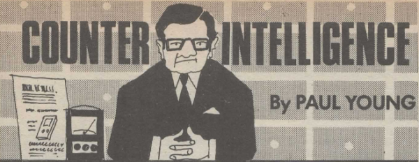
As a child, my favourite regular feature became “Counter Intelligence” by Paul Young. I liked his witty, caustic and grumpy musings on life in the kind of corner electronics shop that was already finding times tough. I remember that dad used to take me to a shop in Leicester staffed by blokes in beige lab-coats stocked with thousands of components in tiny draws. They hardly ever had exactly what you wanted but could usually produce something that would do the job.


The adverts are a real blast from the past. Many of them seemed to run unmodified for years and years. The spiv zapping his light and the odd boy with his crystal set were almost permanent features. I imagine J Bull (Electrical) always doing deals on vast lots of unwanted items and then finding enticing descriptions to sell them off to the unsuspecting.
So, for anyone who, like me, wants to wallow in nostalgia, or just see what the old days were like here is Everyday Electronics August 1981.
-
A nice 3rd party sequencer for the LushOne
Posted on July 23rd, 2017 No comments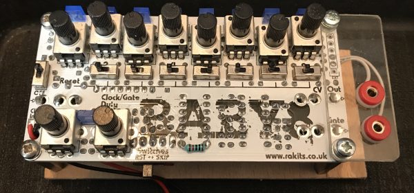
I often get asked “is there a sequencer for the LushOne” and the answer, currently, is “no, because I never got around to designing one”. Of course, the LushOne has slightly non-standard voltages (at least relative to Eurorack norms) which means that a lot of off-the-shelf sequencers need some external adaptors to nicely connect.
I was delighted recently when a customer who had asked about a sequencer sent me a link to the Baby 8 available from Rakits (also in the UK). This little kit is about as close to an ideal beginner’s sequencer for the LushOne as you can get. The output voltages (0V-5V) are compatible with LushOne gate and CV inputs. The power supply voltage is the same as the LushOne and the design is very similar to the “all on the PCB” approach in the LushOne. The only things that are different are the board size and the connectors.
For the connectors, I added a mezzanine board on the side (see photo) to make the outputs accessible with 2mm banana plugs. In my installation, it doesn’t need an external ground connector because it shares the power supply ground with the rest of the system.
It’s a straight-forward kit to build – all based on through-hole components. It uses the classic 4017 sequencer concept, but despite this simplicity it has some nice touches – variable gate pulse width and a gate skip feature on each step. All in all, a nice addition to any LushOne system.
-
A DSONano tile for my LushOne system
Posted on May 1st, 2017 No comments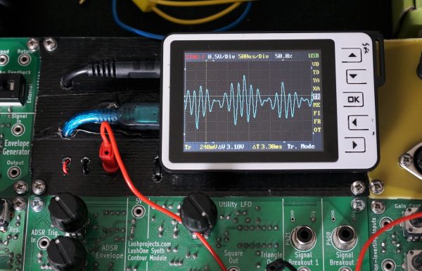
Portable oscilloscopes seems to be a product category where nobody ever gets things quite right. There are some signs that the new generation of tablet-based scopes will finally fix that, but for now we make do as best we can. My portable scope is a DSO-Nano v2 which was a present from my wife. I use third-party software on it which has a lot of improvements compared to the official load but it’s still klunky. Having said that, if you just what to quickly check an audio frequency waveform it really is something you can take anywhere.
I’ve also found the DSO-Nano useful as something I can quickly fire-up to check signals in my LushOne modular synthesizer system. So, having given my synth a permanent home it seemed natural to fill the one empty tile with a mounting for the DSO-Nano.
The tile was made from scrap items and parts-box contents. For the board I used an old prototype LushOne PCB which I covered in black tape to make it look tidy. The DSO-Nano is just held on with velcro so it can easily be detached for other uses. An old USB-mini lead was cut-up and connected to a 5V regulator to provide power to the scope. An old 3.5mm jack lead (broken at one end) was “upcycled” to provide a break-out to the 2mm sockets used in the LushOne.
I like the result – it gives the system a nice feeling of completeness and adds a valuable tool.
-
Sholto builds a cool LushOne case
Posted on October 30th, 2014 No comments
Sholto’s LushOne case
Another excellent case for the LushOne described by Sholto on Instructables. The project work that people do on top of the basic LushOne kits continues to be a delight!
-
My approach to video circuit bending
Posted on April 11th, 2014 No comments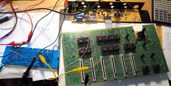 I get asked quite often about how I approach video bending projects, so here are my thoughts. Because I am trained as an electronic engineer my approach is theoretically and technically driven as opposed to the experimental approaches that other people may use. I find this works particularly well with video bending because you need to retain the structure of the video signal if it is going to display properly.
When starting out on a project the first thing I do is to find all the documentation I can about the unit. If I can obtain schematics or service manuals then these can be a great help. For an interesting unit I am happy to buy service manuals if they are not available for free because it saves so much time and hassle. So far it has always been a good investment. If I do get hold of good documentation then examining the circuit will often give me ideas about how things might be modified. Basically I am looking for places where key signals, like the separate RGB colour levels, can be intercepted and modified. There is more discussion on that below.
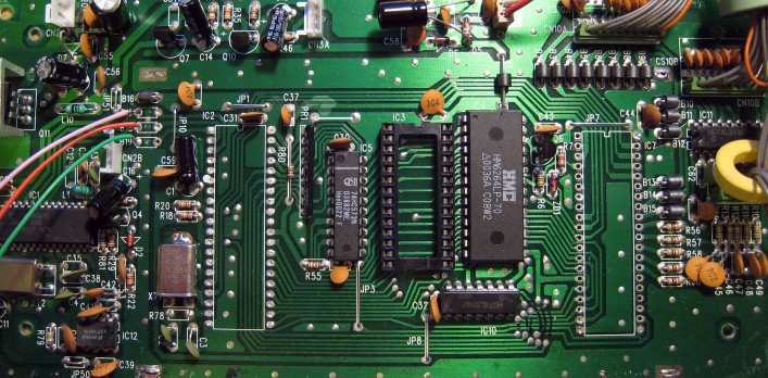
If I don’t have a good manual then I will look at the circuit on the board and try and reverse engineer the key parts. This normally starts with identifying the main chips on the board and through the datasheets and knowledge of the normal operation working out how the signal flows through the circuit. Once you get an idea of the signal flow then you can start to focus in on areas that seem to offer the possibility of modification.
Bending Opportunities
Finding bending opportunities is partly science, partly art and partly gut instinct. You want to find a signal or processing function in the circuit that is amenable to modification. A composite video signal consists of the video information (luminance and colour) combined with synchronization information (horizontal and vertical). In most cases you don’t want to over-distort the synchronization information because this will prevent the signal displaying. Finding opportunities to just modify the video information is important.
For the video signals then a lot of units will separate video and sync information internally. If you can pull out pure luminance, hue or RGB signals from the circuit then you can make these available to process and distort through other circuits without damaging the synchronization. Just additively mixing in audio or other video signals on top of a video signal can be interesting. Some, cheaper, circuits don’t separate the video and sync information and it can be hard to bend the signals for these.
Many video mixers also contain various gate signals that control how different parts of the same picture are processed in different ways. These are used to implement things like wipes and colour fills. Pulling out these gate signals or being able to inject new gate signals can create fantastic effects. Try xoring two gates from different mixers together and then injecting the result back in to the original circuit.
As well as going after the signals you can go after the processing functions. A simple trick is to modify the circuit to remove the limits on how strongly a processing function affects a signal. For example if you have a circuit that controls the colour saturation then it might be possible to boost the gain of this beyond what is intended and create super-saturated and unstable colours in the output.
Another thing I like to do is to see if it is possible to replace manual controls with control voltages. In this way you can sweep control values rapidly, even within one frame of a video, under the control of an external circuit. A lot of effects just come from feeding an audio signal in to a control voltage that varies some aspect of a video signal.
Intellectually I find it more interesting and more satisfying to work with primarily analogue video equipment, but I guess I should add a word on digital equipment. In circuit bending on digital circuits a common technique is just to ground certain address or data signals so that the circuit starts to misbehave. The results are unpredictable, but fun. This approach carries quite a high risk that the outputs of the digital circuits will be damaged as they try and drive a grounded signal “high”. I suspect this is the cause of a lot of equipment damage caused by circuit bending attempts. One reason you can get away with it on some older equipment is that they used NMOS logic. A feature of NMOS is that it has no active pull-up device (just a resistor) so grounding the output is acceptable.
Equipment Safety
People often ask me if I have ever blown anything up while circuit bending. So far the answer is “no”. I think this is largely because I am normally working with a reasonably good idea of how the circuit is meant to operate and I understand what common electronic circuits will and won’t tolerate being done to them. However, circuit bending is a full contact sport. If you can’t tolerate the risk of destroying what you are trying to bend then you shouldn’t have opened the case.
Personal Safety
Personal safety is your responsibility. My very strong preference is to only work on equipment that is powered from a low voltage source or, if it has an internal power supply, where the high voltage elements are fully protected against accidental contact. I recommend you don’t work on designs where high voltage components might be touched.
Older equipment will contain lead, and possibly other unpleasant chemicals. Always take appropriate precautions including through hand-washing before handling food.
I don’t know how much it is possible to teach circuit bending. Particularly with video it is a black-art and relies heavily on experience and luck. Hopefully these hints will help those that want to give it a go though. With a lot of old analogue equipment being sold cheap just get something and start exploring.