Lushprojects Blog
Projects in music, video, art, technology and learning

-
Everyday Electronics Magazine
Posted on March 17th, 2018 No commentsEveryday Electronics magazine is something I have fond memories of from my childhood. Much of the practical knowledge I have of electronics originated from things I read there or stuff I tried to make (some of it DID work). For many years my parents kept-up a subscription for me until sometime in the late-80s when I outgrew it.
There is quite a lot of info online about EE’s sister publication Practical Electronics (which it would eventually merge with to create Everyday Practical Electronics) but I can’t find a lot written about EE. Recently I saw an edition of EE that recognised as one I originally owned in a second hand shop. At 20p it was an easy decision to take home.
EE always put a bit of effort in to the cover which is one thing that makes them memorable. This one with the dodgy looking vicar and his assistant is perhaps memorable for the wrong reasons. The projects are typical of what I remember – endless variations on simple circuits with oscillators, discreet transistors, 4000-series CMOS and op-amps. Even the cover project isn’t that exciting, though if you were in the market for an electronic wheel of fortune I guess it would do the job. They might have been basic and (whisper) not terribly useful but building them was still a great way to learn practical skills.
The features are quite interesting and remarkably well considered in terms of content. Magazines like EE were the main source of information in the pre-Internet era and you can almost see how the different features mirror popular Internet content today. In “For Your Entertainment” Barry Fox makes some interesting comments on the current state of flat-screen displays before getting side-tracked in to a discussion of Sinclair’s doomed flat CRT project. The government didn’t half invest in some rubbish projects in those days. Some of the features do hint towards the tide of consumer electronics that would spell doom for much of the old hobbyist world. Another glimpse of the future is the side-bar on direct broadcasting by satellite in “Radio World”. The introduction of DBS as a platform for Sky TV was a huge step towards today’s media landscape.

As a child, my favourite regular feature became “Counter Intelligence” by Paul Young. I liked his witty, caustic and grumpy musings on life in the kind of corner electronics shop that was already finding times tough. I remember that dad used to take me to a shop in Leicester staffed by blokes in beige lab-coats stocked with thousands of components in tiny draws. They hardly ever had exactly what you wanted but could usually produce something that would do the job.
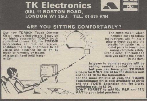
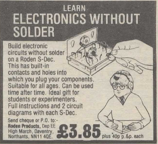
The adverts are a real blast from the past. Many of them seemed to run unmodified for years and years. The spiv zapping his light and the odd boy with his crystal set were almost permanent features. I imagine J Bull (Electrical) always doing deals on vast lots of unwanted items and then finding enticing descriptions to sell them off to the unsuspecting.
So, for anyone who, like me, wants to wallow in nostalgia, or just see what the old days were like here is Everyday Electronics August 1981.

-
The “Electronics Kit” Common Emitter Amp
Posted on August 20th, 2017 No commentsOne project that’s been in my mind for ages is to revisit some of the circuits from my childhood Philips X40 kit. I finally got around to putting “Experiment 5 – Telephone pick-up and amplifier” in to my circuit simulator. This is the first of several audio amplifier circuits in the manual, and they all follow the same design pattern. Similar circuits are also used in other educational kits. I had tried to use this circuit design in my own electronics experiments as a kid. Mostly it didn’t work, but sometimes it did. As an adult, I was interested to understand its characteristics to help explain where it’s appropriate.
View the about in full screen.
Looking at the simulation you will notice the amplifier is non-linear (compare the shape of the top of the sine wave out to the bottom in the output of the first stage). This isn’t unexpected given that transistors have an exponential relationship between the base voltage and the collector current. The biasing on the second stage also looks bad, meaning that the output signal is clipped on the positive side. The simulation result raises several questions in my mind:
- Why is this type of amplifier so popular in basic electronic kits?
- Are they circumstances in which the amplifier is linear?
- What are the characteristics of this type of amplifier anyway?
To answer these questions, let’s look at the basic building block of this amp. It’s a single transistor common emitter configuration. The biasing is from a high value resistor between the collector and the base. Wikipedia informs me that this configuration is called “collector feedback bias“. The signal is coupled in and out of the stage through capacitors.
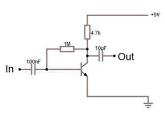
Single Stage of Amplifier
Looking at this circuit you can guess why it’s popular in these kits: the component count is very low. Hence, it is easy for kids to build. If you have an intuitive understanding of transistors, you might also guess that resistor between the collector and the base creates negative feedback giving the circuit the ability to find a suitable operating point across a range of conditions.
As all the textbooks tell you, transistor amplifiers require that the transistor(s) are “biased” correctly to work. The aim of biasing is to set the DC conditions around the transistor so that it is in the “active zone” of operation. The active zone means that you are past the threshold for the base voltage required to start to turn the transistor on, but not yet at the base voltage where the transistor is fully turned on and saturated. The DC conditions that the biasing establishes are called the “operating point”.
As I mentioned, in this circuit the base resistor provides negative feedback which tends to stabilize the operating point. When the circuit is switched on there is no current through the transistor so the collector voltage is at the power supply voltage and the base is pulled high though the two resistors. This rising base voltage turns the transistor on and this pulls the collector voltage down (because of a voltage drop through the collector resistor) which in turn reduces the base voltage – tending to turn the transistor off and reduce the collector current. In practice, these effects will almost instantaneously reach equilibrium with the transistor in a partially on state – i.e. in its active region.
Wikipedia gives a pretty good explanation of how to calculate the operating point so I won’t repeat it. One thing to note though, for the resistor values used in this configuration, the operating point will depend on the gain (β) of the transistor so the operating point will change for different transistors. Here is a graph showing how Vc depends on the gain (β).
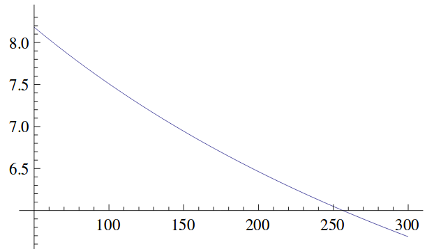
Theoretical Vc (Y axis) Vs Gain (X axis) for Circuit Shown Above
So, that just about wraps-up the situation for the DC bias. It works just about OK as long as you aren’t fussy and don’t expect a big output voltage swing I guess! What about the AC characteristics of this circuit? What is the gain? What about this non-linearity effect?
I checked a few standard text books, and the web, and couldn’t find a theoretical treatment for this circuit configuration so I had to come up with my own. Let’s start by assuming that the impedance of the input source through the coupling resistor is low compared to the input impedance of the amplifier. In that case the input signal becomes just a change in voltage on the base of the transistor (ΔVBE). In that case we can use the Ebers-Moll equation for the transistor to work out the impact on the collector current (and hence the collector voltage). Ebers-Moll says:
IC2/IC1 = Exp( ΔVBE / VT ) Where VT ≈ 25.3mV at room temperature
If you write IC2 = IC1 + ΔIC, and convert the collector current to the corresponding voltage you can get the solution:
ΔVC = ( 1 – Exp( ΔVBE / VT) ) . ( VCC – VC1 )
Where VCC is the power supply voltage and VC1 is the voltage at the collector at the quiescent operating point
That equation fascinates me for two reasons:
- Clearly, this is an exponential amplifier – which explains the non-linearity
- The gain depends on the collector voltage at the quiescent operating point. The graph above which shows how the operating point changes with β translates to changes in the stage gain.
Can we imagine this amp could be approximately linear? Well, as my high-school physics teacher said “everything is linear if you look at a small enough range” (cue sound of 1,000,000 mathematicians groaning). So, we know by Taylor expansion that:
Exp( x ) = 1 + x + x2/2! + x3/3! + …
So, if ΔVBE << VT we can approximate the exponential using just the first two terms above.
ΔVC ≈ – ( ΔVBE ) . ( VCC – VC1 ) / VT
In other words, for very small input signals (<< 25mV) it is kind-of, sort-of, a linear amplifier of gain ( VCC – VC1 ) / VT . Here are some handy plots from Mathics of gain Vs β, Rc and Rb.
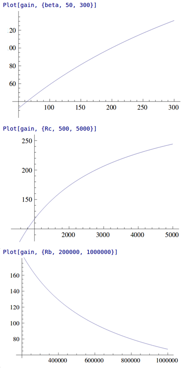
Stage Gain (Y axis) Vs β (Top), Rc (Middle), Rb (Bottom)
Actually, the stage gain in this configuration is quite high, though very dependent on the β of the transistor. I might also remark that the output impedance is poor (limited by Rc ), though, without having done the calculation, I think the input impedance is probably OK.
So, if you want a high gain, single stage, small signal amp with very few components, and, you aren’t too worried about predictability of the gain OR linearity OR output impedance then this circuit just about does the job. This actually fits the bill for these beginner’s electronic kits pretty well. If your requirements are more stringent then better avoid this circuit and look for others. Just one thing still seems odd – why is the second stage bias set where it is on the original circuit?
For me it’s been interesting to look at how much information you can extract about this, fairly trivial, circuit and it’s certainly refreshed my understanding of transistor fundamentals. I hope you find it interesting too.
-
A nice 3rd party sequencer for the LushOne
Posted on July 23rd, 2017 No comments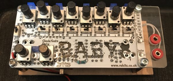
I often get asked “is there a sequencer for the LushOne” and the answer, currently, is “no, because I never got around to designing one”. Of course, the LushOne has slightly non-standard voltages (at least relative to Eurorack norms) which means that a lot of off-the-shelf sequencers need some external adaptors to nicely connect.
I was delighted recently when a customer who had asked about a sequencer sent me a link to the Baby 8 available from Rakits (also in the UK). This little kit is about as close to an ideal beginner’s sequencer for the LushOne as you can get. The output voltages (0V-5V) are compatible with LushOne gate and CV inputs. The power supply voltage is the same as the LushOne and the design is very similar to the “all on the PCB” approach in the LushOne. The only things that are different are the board size and the connectors.
For the connectors, I added a mezzanine board on the side (see photo) to make the outputs accessible with 2mm banana plugs. In my installation, it doesn’t need an external ground connector because it shares the power supply ground with the rest of the system.
It’s a straight-forward kit to build – all based on through-hole components. It uses the classic 4017 sequencer concept, but despite this simplicity it has some nice touches – variable gate pulse width and a gate skip feature on each step. All in all, a nice addition to any LushOne system.
-
A DSONano tile for my LushOne system
Posted on May 1st, 2017 No comments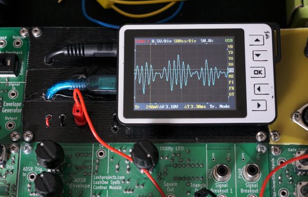
Portable oscilloscopes seems to be a product category where nobody ever gets things quite right. There are some signs that the new generation of tablet-based scopes will finally fix that, but for now we make do as best we can. My portable scope is a DSO-Nano v2 which was a present from my wife. I use third-party software on it which has a lot of improvements compared to the official load but it’s still klunky. Having said that, if you just what to quickly check an audio frequency waveform it really is something you can take anywhere.
I’ve also found the DSO-Nano useful as something I can quickly fire-up to check signals in my LushOne modular synthesizer system. So, having given my synth a permanent home it seemed natural to fill the one empty tile with a mounting for the DSO-Nano.
The tile was made from scrap items and parts-box contents. For the board I used an old prototype LushOne PCB which I covered in black tape to make it look tidy. The DSO-Nano is just held on with velcro so it can easily be detached for other uses. An old USB-mini lead was cut-up and connected to a 5V regulator to provide power to the scope. An old 3.5mm jack lead (broken at one end) was “upcycled” to provide a break-out to the 2mm sockets used in the LushOne.
I like the result – it gives the system a nice feeling of completeness and adds a valuable tool.
-
JavaScript Objects – some key examples
Posted on March 28th, 2017 No commentsSome of the JavaScript handling of objects is pretty wacky IMHO. Here is some code that illustrates some key points:
- Global, private and instance variables
- Privileged and private functions
- How “this” is assigned and how to work around that
See also: http://www.crockford.com/javascript/private.html
Some may point out that my application of OOP terminology to JavaScript isn’t correct. Strictly, what I am showing here are properties of the way JavaScript implements closures, but for people coming from an OOP perspective it’s helpful to be able to understand how to achieve some common OOish goals.
// This is a constructor Test function Test() { // Assign the private instance variable "self" to the value of this in the constructor. // More later on why we want to do this var self=this; // Assign a global variable g (probably not what you want to do in a real object!) g="global"; // Assign a private instance variable p var p = "private"; // Assign an instance variable i self.i = "instance"; // Create a private function pp (can't be accessed form outside the object) function pp () { console.log("pp"); } // Another way of assigning a private function var ppp = function () { console.log("ppp"); } // Create a 'privileged' function (public function that can access private info) this.p = function() { pp(); ppp(); console.log("p="+p); console.log("this.i="+this.i); console.log("self.i="+self.i); } } i="global i"; // assign i as a global o1 = new Test(); // o1.pp(); - would be an error - pp is private "o1.pp is not a function" // o1.ppp(); - would be an error - ppp is private. o1.p(); // Outputs 'pp', 'ppp', 'p=private', 'this.i=instance' and 'self.i=instance' console.log("Now with a call-back"); setTimeout(o1.p, 1000); // outputs 'pp', 'ppp', 'p=private', 'this.i=global i' and 'self.i=instance' // What's going on - // In the callback case the "this" is set to the current context which in this case is // the global document - hence getting the global "i" instead of the instance variable "i". // To get the instance variable i we want the value of "this" which was used during the // constructor which is stored in "self". -
LushOne Synth – Briefcase Install
Posted on February 14th, 2017 No commentsJust a short video about the installation of my LushOne synth system in a briefcase to make a really neat, and unique, portable modular.
-
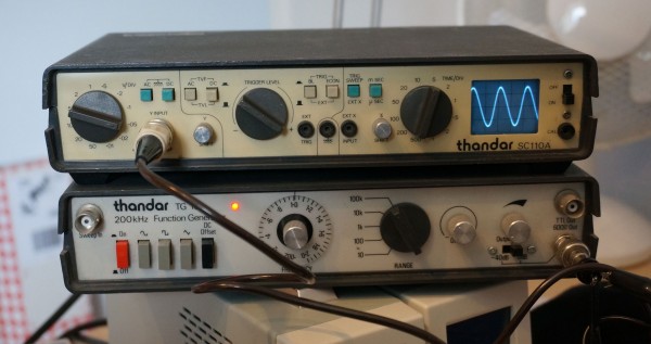
Fixing the cutest proper scope – Sincair/Thandar SC110A
Posted on July 31st, 2015 No commentsWhen doing some research on the web about my Philips X.40 electronics teaching kit I found out about the contemporary Philips EE2007 kit which had a battery operated CRT for the teenage nerd to play with. Just how cool is that? Even as an adult I immediately wanted something similar. The schematics of the EE2007 CRT module are easily available and I thought about building a clone using modern components but, to be honest, I am a bit of a scardy -cat when it comes to high voltages and I didn’t fancy getting to grips with the HT supply. Like so many others the project went on the back-burner.
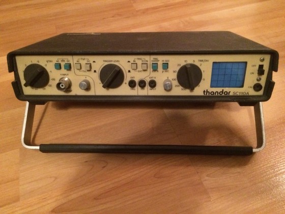
The original eBay photo – looks OK
Recently though I was thinking about upgrading my boat-anchor oscilloscope (it’s a 1980s(?) high-spec Hitachi hybrid analogue/sampling scope which is a joy to use but massive and very limited by today’s digital standards) and I thought I might be able to get a second hand modernish digital scope on eBay without spending too much. I didn’t find the ideal match there, but I did see a Thandar SC110A miniature analogue scope. It was love at first sight – a battery powered scope in a small, smart enclosure that matches my function generator which is always on my electronics bench. Some people find kittens cute but, for me, this dolls-house scope with its tiny 4cm diagonal screen just makes me feel all squeeeeeeeeeee. In XY mode I could use it like the EE2007 CRT but with added convenience of calibrated amplifiers and a timebase (no intensity input though).
The scope was described as working but I was always sceptical because eBayers are often economical with the truth and anyway not many people would know how to test it properly. Without being cheap it was at a price that I was prepared to spend for a bit of fun so I bought it expecting I would have to do some remedial work. When I got it there was good news and bad news. Good news was that you could get a “bright line” trace with no signal and most of the functions seemed to do vaguely the right thing. Bad news was that the display had awful distortion and freaky interactions between the X and Y axis. Also some of the input ranges on the Y axis didn’t seem to work. Time for fault-finding and recalibration using the handily supplied service manual.
To do the calibration you turn the scope upside down and take the bottom half of the case off which exposes the main circuit board and calibration controls. Once inside you see that the circuit board is actually branded Sinclair so you will understand if I was suspicious that it could ever be made to work properly at all. In fact Thandar and Sinclair seemed to have cooperated on several test instruments. Sinclair seems to have picked up the case mouldings from Thandar and Thandar sold several Sinclair instruments under their own brand (brave decision). This design seems to have originated in Sinclair and the CRT, as we will see, was custom made for Sinclair for their microvision pocket TVs.
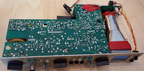
Ready for repair
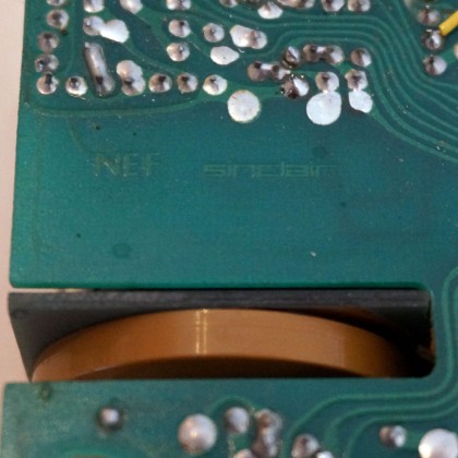
The mark of the devil
When I powered the scope up to calibrate it I realized that it had a fault that I had never seen before in any device. It worked, to an extent, the right way up but when you turned it upside down the trace disappeared and the whole thing seemed dead. I spent a long time turning the machine one way and then the other trying to find out where the thing stopped working and where the fault might me. Eventually I heard a little tinkle that seemed to come from inside the CRT which alerted me to the real cause. Sometimes electronic debugging involves all your senses. Removing the screening foils and looking inside the CRT I found that the glass supports holding one of the Y axis deflection plates and place had broken it the electrode was just flopping around – coming in to contact with other electrodes when the scope was turned upside down. Humm – eBay seller was dodgy on that one IMHO. Still, at least we have a plausible explanation for many of the problems.
Now, where do you get a custom made Sinclair CRT from in 2015? A few specialist shops had them listed at silly prices and were out of stock anyway. Then I had an inspiration – my searches had told me that the Sinclair Microvision TVs used the same tube so perhaps I could get one of those and cannibalize it. Back to eBay and, yes, there was a suitable Micovision for sale at not too high a price.
While waiting for the Microvision to arrive I did the best to fix the other problems working with the dodgy tube. To do this I had to strip the case off completely so I could run it the right way up and still access the controls. As a matter of routine I decided to replace all the polar capacitors (tants and electrolytics) in the design. It has a switching power supply which is nice and compact and gives it a very wide tolerance of supply voltages. In my experience switching power supplies were pretty rare at the time so this might have been a brave design. Normally in test equipment you see a lot of effort going in to conditioning the power supplies with great big capacitors to smooth them. In a sign of classic Sinclair cost-cutting the biggest supply capacitor in this scope is 47uF. It seems to work well enough though.
Next I turned my attention to the dead ranges on the Y Axis. . I spent a long time investigating possible faults with the switch or problems with the Y input buffer. In fact I should have checked the obvious. There is a “DC Offset” trim which needs to be set right to get the input buffer working correctly on all ranges. RTFM applies here.
After a few days my Microvision arrives in the post. I have to say it does look like a proper gadget and must have been quite a cool thing when it was new. As far as I can tell, with no suitable source for a modulated analogue TV signal available, it worked fine. Inside it’s in good condition and there is a surprising amount of space in the case. I feel a bit bad about whipping its tube out and swapping it for the broken one from the scope but I reckon it’s better to have one useful device that works than a TV that is no longer usable in the digital era.

My Sinclair Microvision
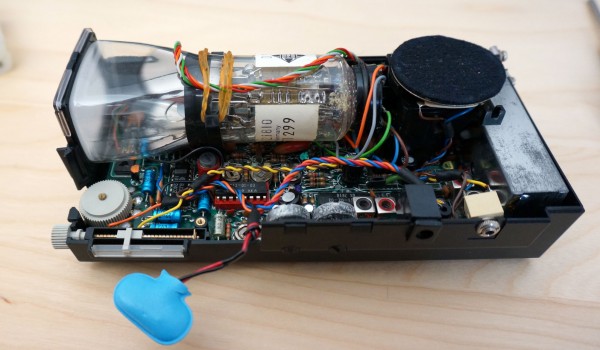
Interior of Sinclair Microvision with the precious tube
With the new tube in and the polar capacitors replaced the scope is working a lot better. Almost everything seems fine except that the Y signal is still very distorted. My fear at this stage is that the shorted electrode in the old tube has damaged some components in the Y amplifier and it’s going to need a lot of debugging and component sourcing to sort it out. In a moment of inspiration I wondered if looking at the lissajous figure from feeding the same signal to X and Y might be useful to understand what was going wrong. Instead of the expected straight line I saw a very definite knee – like some part of the amp was saturating. It turns out that setting up the calibration for the Y amplifier involves two interacting gain controls. The previous person to set this up had set one way too high and the other way too low forcing the amp in to saturation and clipping. Once both had been reset to near their midpoints the amp worked just fine. To be fair the service manual doesn’t explain how to set these controls very well and it requires a bit of electronics experience to know what you are supposed to do.
Aren’t they cute?!
With the Y amplifier recalibrated everything now works very nicely. Technically it’s certainly not a great scope but its simplicity is lovely. The tiny size is very practical. I like the immediacy of analogue scopes. You interact with them much more by intuition rather than digital scopes where you have to think. For answering the eternal electronic engineering question, “do I have a signal here?”, on my audio circuits it will be very handy. As I nice final touch I made a lead so I can use a USB battery booster that I got as a freebe from a trade-show as a power supply. It should run for about 10 hours on a charge. It’s just a really nice thing! I’ll maybe think about whether I can add an external control for the intensity and perhaps do a DIY TV on it.
Updates – 2022 – More History, Notes, Upgrades
I’ve been learning a few new things about this ‘scope recently which are worth saving, and also done some upgrades that I want to mention.
The SC110A CRT isn’t actually a Sinclair product – it was made by Telefunken and has model number D5-100W. In fact, the SC110A isn’t the only scope that used the CRT. Incredibly, a company in California called Non Linear Systems (NLS) made a two channel scope. Given how hard it is to properly see a single channel on that tiny CRT, it must be quite an experience to try and view two at once.
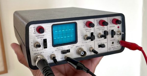
NLS MS-215 Scope – photo from Mohit Bhoite on Twitter An Upgrade for the SC110A (No Soldering Required)
The rotary knobs have a very small molding on one end to show what they are pointing to. These are almost invisible in use, and you can’t tell which end of the pointer you should be looking at. Put something very visible on the active end of the pointer to help read the dials.
Triggering
The trigger control on the SC110A is odd in that it uses different parts of the range for +ve and -ve triggering – normally this is done with a separate switch. On most scopes you would set the trigger control to the centre as a starting point to find the right trigger position. On the SC110A the middle position is actually the transition between +ve and -ve triggering and therefore not actually useful. The equivent to a normal “middle” position would be about 3 o’clock or 9 o’clock depending on whether you want +ve or -ve triggering. So, keep this in mind when trying to dial-in the trigger.
In fact the whole triggering system is rather hard to adjust and not very well scaled. At least on my scope a lot of the range of the trigger control is mostly useless. It looks like the circuit design can have a lot of variability in where the trigger lands, so to accommodate this they put a lot of “slop” in the trigger control.
I build a model of the trigger circuit in circuitjs to understand it better.
Based on the model and measurements on my scope, I’ve changed R4 from 10k to 13k in mine to try and make more of the trigger adjustment range useful.
Calibrated X Input
The manual for the SC110A says the X input is about 0.5V/division, but doesn’t give any calibration process for the input. I was doing some experiments with X-Y mode on the scope and wanted the X input to have a known scale. When I measured my scope the X input was more like 0.4V/dvision. It turns out that there are separate adjustments in the scope for the timebase speed and the X amplifier scale, so it is possible to adjust the X input to a precise value, it’s just that the calibration procedure doesn’t give a process.
I made my own adjustment by first adjusting the X amplifier gain so that the X input was on 0.5V/division, and then adjusting the timebase to run correctly using the process in the service manual.
-
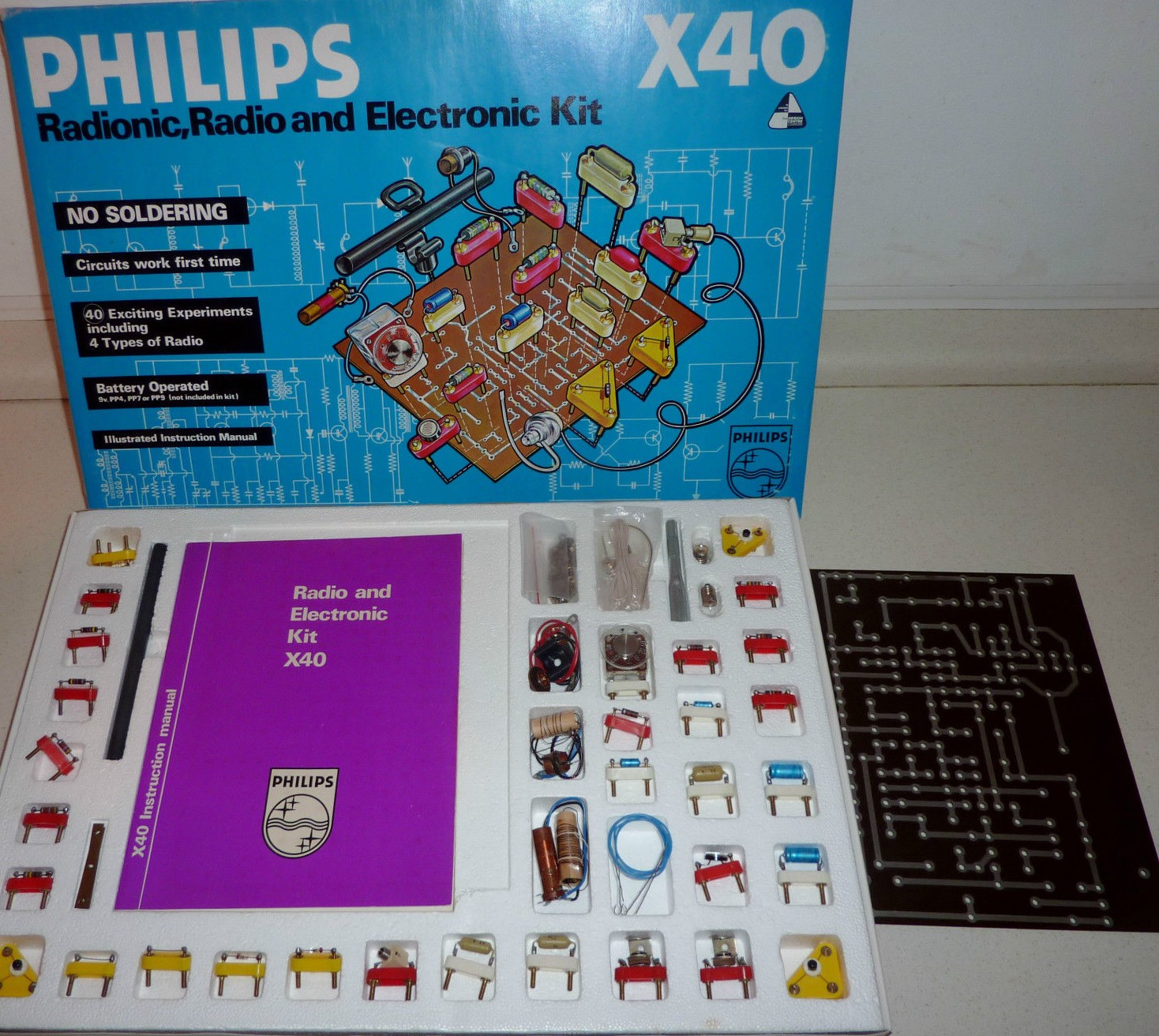
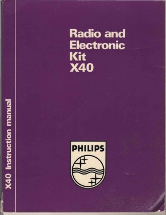
Philips Radionics X40 Kit for Children
Posted on February 12th, 2015 No commentsMum and dad were always very generous to me, particularly when it came to toys that allowed me to explore my obsession with experimentation and construction. As quite young child I had got the “starter” Philips X20 electronics kit, which I played with a lot. Not too long afterwards, sometime in the late 1970s, and still as a pre-teen, I got the monster Philips Radionics X40 kit for my birthday.

Not my kit – my box is long-gone, but one from ebay in almost new condition.
For a child excited by technology (in a hands-on way, not the XBOX, iPad, App-store version of technology that many kids love today) the X40 was an impressive and exciting toy. It allowed you to build 40 projects – called “Experiments” in the manual – from testing to see whether water was conductive (boring) to regenerative radio receivers. The radios were the things I loved the best, particularly when dad and I had made special coils and we could tune it to get SW broadcasts. In the pre-Internet era hearing Voice of America and Radio Tirana was exciting.
As well as the radios the kit had some simple digital electronics. I learnt the function of all the basic logic gates from the X40. I also particularly remember a project which was a multivibrator driving a frequency divider. That project used all four transistors in the kit and seemed particularly sophisticated.
Dad put a lot of thought in to which system to buy and I think he liked the Radionics kit because it was open to expansion and the construction technique was very much like real electronics. The kit came with a large (A4 sized) PCB which was cleverly designed to work with all the projects. The components were mounted on plastic bases with brass screws that went through holes in the PCB to make the connections. Basically it was a solderless version of through-hole PCB construction and you got to see the real components pretty much unpackaged. When I went on to building projects on breadboard and veroboard it was an easy transition because I was so familiar with what things looked like from the X40.
I can’t claim that all the time I spent with the X40 taught me much about electronics theory. Even now I find the lumps of theory dished out in the manual rather hard to follow. At the time they were way over my head. What I did learn was a lot about practical electronics and also that electronics was an experimental science – you could just try changing stuff and seeing what worked. Also the presentation of the manual with the circuit diagrams and the physical layout side-by-side taught me to read circuit diagrams intuitively and that’s a skill that’s been really useful.
The connection with Philips seems to be a bit tenuous by the way. The X40 and other kits in the same range were rather confusingly co-branded “Philips” and “Radionics”. Philips had their own range of kits that was popular in Europe and as far as I can tell the X40 was a created by the UK Radionic company who I guess then applied the Philips brand under licence.
For the fundamentals of electronics using bipolar transistors I still think that the basic outline and structure of the X40 projects is very appropriate, so much so in fact that when I designed by Electronics for Absolute Beginners course I took the X40 as the initial starting point.
I still have the components and manual for my X40 kit – one day I’ll have to build some circuits to show you. In the meantime, here is a scan of my manual (48MB to it’s big!).
X40 Manual
I am not the only fan of the X40 on the web. Try these sites for more info, photos and manual scans:
- http://www.hansotten.com/index.php?page=x40
- http://ee.old.no/radionic/
- http://ee.old.no/library/ (Radionic scans near the bottom)
-
Sholto builds a cool LushOne case
Posted on October 30th, 2014 No comments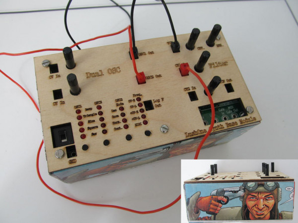
Sholto’s LushOne case
Another excellent case for the LushOne described by Sholto on Instructables. The project work that people do on top of the basic LushOne kits continues to be a delight!
-
Vactrols and replacing variable resistors with control voltages
Posted on August 3rd, 2014 No commentsIn a lot of electronic audio circuits the response is controlled by a variable resistor rather than a control voltage (CV). If you want to adapt these circuits to use in a modular configuration then you often feel it would be nice to replace or augment the variable resistor with a control voltage input. In some cases this can be quite easy – the variable resistor might just be set up as a voltage divider between two DC levels and effectively the output of the wiper is a control voltage. However it is often the case that the variable resistor is actually manipulating a waveform inside the circuit. For example, in a lot of filter designs the resonance level works on a variable resistance controlling the amount of positive feedback from the output to the input and this isn’t easily replaced with a control voltage.
I recently got this question from the web:
I want to add external CV [control voltage] control to an existing circuit. It’s to control the resonance of a filter where there’s already a pot to do this manually. My first idea was to use a vactrol and run the resistance from that in sequence with the pot with the pot then acting as an offset whenever there’s CV applied. However there’s a few things I’m struggling with.
1) It’s always only going to be a positive offset, even if you feed a bipolar signal to the CV, being that the vactrol can’t output negative resistance 🙂
2) What’s the strategy for managing current limits going to the vactrol? I’m familiar with *reducing* current via resistance but what if you don’t actually know what the current is going to be? How do you bring it within a usable range?
3) The big question: is this the best way to achieve the original aim? Any other suggestions?This question nicely captures the classic problems in this situation – there isn’t an easy general purpose way of changing a control voltage in to a variable resistance. The simplest approach, as suggested here, is to use a vactrol. For those not familiar with the term a vactrol is a light pointing at a light dependent resistor in a sealed unit. By connecting the control voltage to the light you generate a variable resistance that depends on the control voltage while keeping the control voltage electrically isolated from the resistance.
Vactrols are easy to use but have lots of limitations – they don’t have a well defined relationship between the CV and the resistance and the range of resistance values achieved may not match what you want in your application. Generally they also have quite slow response. There isn’t much you can do about these limitations. Some kind of preprocessing of the CV might help set the range of resistances achieved to better meet your needs. You will also want to introduce the light dependent resistor in to the circuit with some kind of additional adjustment (perhaps the existing control) to set the control-point it is working around. For example, to get a bipolar response (Q1 above) you can add a DC offset to the CV so that the bipolar signal becomes an alternating positive signal and then set the adjusting resistor to position the range of the output to be that you are interested in. You can try putting the vactrol in series with the adjusting resistor instead of in parallel.
As far as I know most vactrols will go down close to 0 Ohms resistance when the controlling light is fully-on. This gives you the lower bound for the resistance, and hence upper bound for the in-circuit current. As just about all variable resistors also go to 0 Ohms you can pretty much add a vactrol in series or parallel with an existing variable resistor from the point of view of the minimum resistance (Q2). If you don’t want the vactrol to drop to 0 Ohms put a resistor in series with it, or manipulate the CV to limit how large the signal feeding the vactrol’s lamp gets.
As for Q3 – no, sorry there isn’t a general way of replacing resistance-driven circuits with CVs. There are various circuits that are called voltage-to-resistance converters (eg see the LM13700 datasheet) but in reality these have complicated limitations on how they can be used and don’t fully isolate the CV from the rest of the circuit. Unless you know a lot about how the circuit you are modifying works and fully understand the limitations it is hard to retrospectively introduce these in to an existing design that uses a mechanical variable resistor. If you *really* want a solution you could have a servo-motor turning a mechanical variable resistor – I can remember a few hi-fi buff friendly amps that used this approach.
Normally though the best you can do is to experiment with different ways of using a vactrol and learn to love their limitations. Any technical defects are called “character” and in classic audio equipment people pay good money for them!