-
Time to go home – No longer on Southwold Pier
Posted on February 4th, 2011 No commentsWell folks – all good things must come to an end. Southwold Pier are having a reorganization and have decided it’s time to swap things around in the arcade. Long at the short of it is Lunar Lander and Cyclepong are going to come home this weekend. Back to the workshop to see what several years of heavy use on the pier has done to them.
For those that want a change to play them this year then look out for them at MakerFaire UK 2011.
-
Solder Soldiers v2.0
Posted on July 2nd, 2010 No comments
Solder Soldiers v2.0 took place in Leicester in June. Check out the gallery linked above for the cool stuff on display.
I was asked to perform on the opening night.
-
Glitch – A film about circuit bending
Posted on June 16th, 2010 No commentsMe (and my stuff) crop up nicely in this short film
-
Video bends on film
Posted on March 30th, 2010 No commentsNice documentary about the last circuit bending workshop at South Hill Park. I am in the middle talking about video circuit bending with a few demos too.
-
Extra bends on GSC AVEP2S
Posted on March 23rd, 2010 No commentsThe circuit-bent AVEP2S is still my favourite video tool. I was looking at some other video circuit benders work and liked a lot of stuff they were doing with chroma keys and control of saturation in an image. This inspired me to go back to the AVEP2S and add a few other nice features.
The first project was to add some simple chroma key functions. The signals that were easily available to do this are the PAL colour components “(R-Y)” and “(B-Y)” so they aren’t real chroma keys because there is a big component of luminance in them too. Still they help slice up the image. The keying circuit is built from a uA733 video amp (from the arc) to boost the signals feeding in to a comparator. I found the 733 amp really hard to work with – it seems very sensitive to DC biasing and impedance on the output. Any advice from readers on how to make effective use of this IC is welcome.
The other mod was to provide an input that can override the manual colour saturation control so that output can be varied dynamically.

Squeezing the Chroma Key Controls On The AVEP2S Case
With the additional keys you can get some really nice effects – particularly as you can modulate the key with an audio signal.

Screen Capture with Aditional Chroma Key
-
Videobending Utility Functions
Posted on March 22nd, 2010 No commentsI’ve used the spare half of the Down The Bar case to house some utility functions that are useful for getting effects on video bends.
The functions are:
- Two voltage controlled amplifiers based on this design
- Sum/difference amplifier for the output of the two VCAs
- Schmitt trigger with controllable threshold and hysteresis
- Analog meters to show the DC level and AC level of the output from the sum/difference amp
Two 555-based LFOs
With all this to hand the you can create a lot richer effects, and the LFOs allow some “hands free” dynamic effects.

Video Bending Utility Functions
-
Riverbed Road
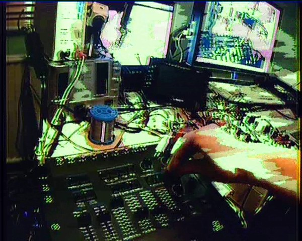
Posted on February 5th, 2010 No commentsAttempting to do something gentle with the video circuit bend machinery – here’s Animat’s lovely Riverbed Road with Sharpie TV visuals. Featuring the Sony Family Studio in a supporting role.
Still learning how to make best use of the equipment – just from watching this I see 100 ways to improve!
Edit: Here is all the equipment used to make the above. Hope you like the flowery table cloth.

River Bed Road Video Bending Equipment
-
Exploring the Sony XV-T33F “Family Studio”
Posted on December 29th, 2009 No commentsI saw this beauty on eBay and it looked so good that even without knowing anything I wanted it. It’s a Sony Family Studio XV-T33F which allows text and graphics to be overlaid on to an incoming video. It’s all driven through the touch-pad interface.

When it arrived I rushed to plug it in. All looks good until I start trying to draw – though the smaller buttons work the big touch pad in the middle doesn’t do anything! Disaster! A bit of work with Google and my own observation provides a solution – find the connector to the flexible plastic PCB on the daughter board inside – open and then reconnect this. It seems to be a common problem that this connector fails to make proper contact. My machine was missing screws in the base and it looked like it had been opened before – I wander if the problem is not a new one. Anyway with the connector reseated everything is working. It really is a blast from the past with vivid blocky graphics all based around the Japanese MSX standard.
Now that everything works it’s time to break it again. Andrew Coleman has some really good info on his blog about the architecture and bending possibilities of the XV-T33F. I would only argue with one thing in his comments. He identifies the three main chips on the logic board and explains two of them – the third (labelled Sony LH534HSY) he suggests is the video overlay chip. I’ve looked at this some more and I am convinced it’s not an overlay controller. It appears to be a mask-programmed ROM for the Z80 CPU based on the Sharp LH534B00 IC. The video mixing is done entirely on the second board in the base.

Logic board on Sony XV-T33F
Andrew suggests various bends by shorting-out different pins on the MSX video chip, and they do indeed work very nicely. As an engineer though I was interested to know why this process doesn’t just blow-up the chip. ICs don’t normally like having outputs shorted together. It turns out that the MSX chip (and I assume the RAM too) are based on the NMOS logic family. The interesting property of NMOS for this purpose is that outputs can be pulled to ground by an external component without any damage. Connecting multiple outputs creates a “wire NOR” effect. So I think Andrew’s bends are safe with one exception. NMOS outputs won’t like being pulled up to a hard “VCC” as this will put the transistors under a lot of stress. VCC on the MSC chip is on pin 58 which is one of the pins Andrew suggests using for bending. I haven’t tried myself (and nor do I plan to), but if you care about your MSX IC I wouldn’t try connecting this pin to any of the outputs.

Main boards on Sony XV-T33F
The video mixing board on the XV-T33F isn’t very easy to understand. There are a lot of different video processing chips and lots of TTL analog switches that route things in different directions. It appears to operate in different modes depending on whether the input is composite or S-video (the XV-T33F doesn’t generate S-video output if it only has composite input). There are a number of buttons and one switch on the board which I assume are there as part of the manufacturing testing process. Pressing the buttons produces various interesting distortions, but it often also breaks the sync in the video signal. I am not sure I will be using that as a bend.
One thing that is interesting is trying to work out the signals on the connectors between the two boards. There are two 10 way connectors that are labelled “CN4” and “CN5” on the logic board. Pin numbering is shown on the video mixing board. Here is my assessment of the functions:
Connector CN4:
1: Ground
2: Red video from logic board
3: Ground
4: Dunno
5: Dunno
6: Dunno
7: Overlay on/off – Low = logic board output, High = Video
8: Some kind of HSYNC I think
9: Dunno
10: DunnoConnector CN5:
1: Ground
2: Dunno
3: Dunno
4: Power
5: Power
6: Power
7: Ground
8: Blue video from logic board
9: Ground
10: Green video from logic boardThis information provides some interesting bending possibilities. I plan to cut the R/G/B video signals and the overlay signal to allow these to be modified or processed as they go through.
-
Circuit Bending with ASMO at South Hill Park
Posted on November 30th, 2009 No commentsI went along to the last afternoon of Stu “ASMO” Smith’s circuit bending workshop at South Hill Park in Bracknell on Sunday. Everybody was busy building sequenced APCs like mad. I came along and did some video bending along with their output.
-
Video circuit bending
Posted on November 22nd, 2009 No commentsA post for the RSS followers – up on the main site is a new page for my circuit bent video mixers – including a new YouTube video for the latest completed project.