

-
LushOne Contour is here!
Posted on October 28th, 2012 No commentsAfter what seems like ages the second module for the LushOne synth is here. The LushOne contour has been in development for the last few months and was slightly delayed due to a few good ideas that arrived too late to be included in the first version of the PCB. Fortunately it was worth the wait, the production version adds a lot of cool effects to the base unit and just the two units together make a very flexible and useful synth. I can see I am going to spend the next few weeks playing with it to find the range of capabilities.
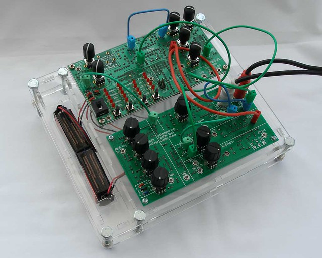
Here is my version in a laser cut case. It’s a really nice thing and it feels great to have got it this far.
-
Latest LushOne Photos
Posted on October 20th, 2012 No commentsA couple of new LushOne photos for fans.
Firstly a nice modification by Felix Hüsken in Cologne who has modified his LushOne to provide 3.5mm connections so he can patch in to his MFB Nanozwerg. Lots of synth tech on his YouTube channel.

I am still working away on the second module – the LushOne Contour. Below we’ve got two prototypes and a laser-cut double case that holds both the LushOne Base and the Contour. Second version of prototype PCBs for the Contour is in production.

-
LM13700 OTA – The missing forumla
Posted on August 15th, 2012 No commentsIf you do anything with analogue syths you quickly run in to the Operational Transconductance Amplifier (OTA) as a key component. These are amps whose current output depends on the voltage difference at the inputs and a control current that scales the gain. They are used for voltage controlled filters, voltage controlled amplifiers and oscillators. The subject of OTAs has a complicated and initially frightening set of assumptions, concepts and implicit ideas around it and getting a handle on the whole thing takes some effort. This blog post isn’t a general introduction to OTAs but it talks about how I solved a particular problem in my understanding and spotted a mistake in one of the common write-ups.
Digital techniques are replacing a lot of OTA applications and OTA chips are being discontinued like there is no tomorrow. One that is still available (and I use in the LushOne) is the venerable LM13700. While designing a voltage controlled amplifier and ring-modulator for the LushOne I found I needed to get a deeper understanding of the LM13700 than I had had before and started to explore the behaviour of the chip in detail. In particular I wanted to be able to predict the gain when the linearization diodes are in use.
The obvious place to turn is the LM13700 data sheet. This is kind-of famous because the designers tried to pack a lot of information and examples of their great new device in but the commercial pressures meant the datasheet needed to be kept short. It is therefore rather compactly written and understanding the example circuits is often an exercise for the reader. Initially though the case I was interested in seemed simple enough. The data sheet provides a nice equation with the glowing claim “no approximations have been made”.

What do all the terms mean? IABC is the amp bias current (pin 1 or 16). ID is the diode bias current (pin 2 or 15). What is IS though? Fortunately Figure 1 of the data sheet tries to tell you – IS is the current being injected in to one input of the amplifier while the other input is grounded. So it all looks nice and simple – except that on the bench the gain I got was about half what I would have expected from this forumulat. In other words the figure of 2 in the numerator seems wrong! Getting to the bottom of this involved a lot of head-scratching and measuring and simulation. Once there the answer is obvious, but at the time it was a big mystery.

I should say at this point that the LM13700 datasheet is absolutely technically correct, but it is rather easy to misunderstand if you don’t apply your brain sufficiently. The problem lies in the interpretation of IS in a real configuration. Normal configuration (and I think any practical use of the LM13700) doesn’t use current sources to set IS and ID/2 at the input as shown above. You use resistors. This makes the real configuration look more like the figure below which is copied out of a couple of magazine articles by Ray Marston that crib heavily from the data sheet. Unfortunately though he has usefully shown the practical configuration the current flows shown are absolutely wrong for this set-up.

The problem is translating the datasheet theoretical diagram in to the real implementation. An easy thing is to assume (as shown above) that IS is the current through R4 and the rest of the datasheet assumptions then apply leading to IOUT = 2 . IS . IABC / ID. What this overlooks is the role of the ID/2 current sink shown in the datasheet figure. In the data sheet the IS and ID/2 current sources/sinks together force the current in one leg to be ID/2 – IS and this forces the other leg to be ID/2 + IS. When you use a resistor to ground instead of a current sink then the relationship between the current in the two legs changes and the system gain becomes different as well.

Simulation and also careful consideration reveals then when you input a current in one leg in the practical system the effect is to increase the current flowing through both R1 and R2. Let’s try and do some analysis – I have used a new term IG for the input current to remove confusion with IS. I’ve also neglected any currents going in to the base of the transistors that form the differential amplifier. The voltages at the cathode (pointy end) of the two diodes (V1, V2) are approximately equal because a forward biased diode is a rough voltage reference – which means the currents IR1 and IR2 are also approximately equal.
ID1 + ID2 = ID
and ID2 = IR2
and ID1 + IG = IR1
Therefore if IR1 ≈ IR2:
ID2 ≈ ID1 + IG
Or (ID2 – ID1) ≈ IG
and ID1 ≈ ID/2 – IG/2
and ID2 ≈ ID/2 + IG/2
So compared to the Marston diagram the difference in the currents is half that predicted. Assuming the ratio ID1 to ID2 drives the output this makes the system gain:

which fits with roughly the measured results.
So, now do we have the missing equation for the LM13700 gain in its most common configuration? Well the answer is (very) “roughly”! If you are on the ball you will notice that if V1 really was the same as V2 then the differential amplifier would have no differential input and therefore zero output. It is precisely the difference in V1 and V2 that drives the output! Hence the assumption that V1≈ V2 the above derivation is dodgy. All I can say is that from experience and simulation it seems to be OK as long as IG << ID and R1 and R2 are reasonably large. With R1=R2=470 Ohms then the simulated gain is about 12% less than the above formula would suggest. For my applications I always have adjustments to allow the user to set the gain and therefore the above formula is good enough to set the component vaues to give the desired range of adjustment. I suspect if you wrote out the maths properly and did the function expansions you could justify the approximations better and understand exactly how factors like the value of R1 and R2 impact the gain.
From deconstructing what went wrong and fixing my (and it seems others’) faulty assumptions I learnt an incredible amount about the LM13700 operation. What’s the moral here?
1) If a data sheet is obviously written with precision then read it with precision.
2) If there is an interpretation trap then you may not be the only person to fall in to it!
Update (2017)
You can now see the two circuits (datasheet version and “typical” configuration) simulated in the browser here:
http://lushprojects.com/circuitjs/circuitjs.html?startCircuit=ota-gain.txt
-
A modular synth that won’t break the bank (Part 2)
Posted on March 25th, 2012 No commentsRethinking modular synth system design
I was out at Megadork at the Love Bytes festival in Sheffield on Friday and they had one of the original designers of the Reactable speaking. He explained it in terms of being a modular synth. It does look cool, but it also seems strange to build a tangible computer simulation of an already tangible entity. Programmers will program I guess. Solderers will solder.
In part 1 of this series I wrote about how my quest for a beginner-priced modular synthesizer started me on the road to fight design flab and reduce costs. How could a cheaper modular synth differ from the standard offerings? It seemed to me that the classic design of a rack with many individual modules was always going to be an expensive solution. I wanted something that could still be used in a modular way but where the modules were bigger pieces of the design and the mounting was lower cost.

EMS Synth-E
Researching in to the history of modular synths I came across an obscure teaching product called the EMS Synthi E from 1975. Designed for school and colleges this is a perfect little modular synth built in to a suitcase. It doesn’t do anything too fancy but it has all the core functions needed to get started creating analogue sounds. If it was still available I would have gone out and bought it. As it isn’t available I decided to take the idea of packaging the basic parts in to a self-contained but still expandable system as the basis for my design.
The next challenge was to think about the simplest useful set of functions. The goal was to have something that could start really small and grow. With this in mind the Korg Monotron was the inspiration behind the first module. The Monotron proves that two oscillators and a filter can be a great instrument and a lot of fun to play with and those are the functions I decided to put in the base module. The current prototype design for the base module has the following features:
- Primary oscillator with square, triangle, sine, ramp and sawtooth waves
- Secondary oscillator which either tracks the primary or acts as a Low Frequency Oscillator (LFO)
- Voltage controlled low-pass filter with resonance and cut-off control
How might the other modules look? This is my rough thinking:
- Amplitude based functions: Envelope generator, Voltage controlled amplifier/ring modulator and extra oscillator
- Signal interfacing functions: signal processor and amplifiers, mixer, delay(?)
- Enhanced filters: band pass, band stop, notch and high pass

MS7 Module Plan
Another barrier to cheap systems is the split-rail power supply that most modular synths need. The power supply on its own often costs more than I want to get the first module out for. My solution: two 9V batteries. It’s a hack, but it gives you something that is simple and portable.
What else might change at the system level? Well, I had to make some decisions about signal levels and MIDI support. Tune in to part 3 soon to lean about those aspects.
-
A modular synth that won’t break the bank (Part 1)
Posted on March 18th, 2012 No commentsThis is part 1 of a series of blog posts about the development of the MS7 Synth.
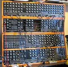
I love looking at and thinking about modular synths like the one above. With tons of wires, knobs, connectors and analogue electronics how could anyone not want one? The problem is that I’ve never been able to convince myself to shell-out what they cost. Various companies have come in and reduced prices but the cost of an “entry” system still typically more than $2000. If you are an enthusiast then those systems are good value but for a beginner or a casual user that is the kind of money that is hard to justify for a bit of fun. I wanted to build something that was cheaper but still capable.A modular synthesizer provides many different analogue electronic modules that can be joined together (“patched”) a multitude of different combinations to manipulate signals and generate sounds. When they first came out in the 1970s they achieved a cult following and massive modular synths became familiar in Prog Rock groups like “Emerson, Lake & Palmer”. Over time their popularity diminished partly as a backlash against the excesses of Prog Rock and partly due to integrated analogue synths like the Mini Moog and then the superior functionality of digital synths. More recently there has been a revival in interest in modular synthesizers and several new small companies have started making them.
What drives this interest in a 40 year old technology when computers can synthesize any sound and emulate analogue beasts that few of us can afford? Partly it is a pull towards retro technology that isn’t just about a screen and keyboard. Partly it is the agreeable roughness of real analogue components. The behaviour of analogue modules drifts over time. When the get overloaded they start to fail in interesting ways. As an electronic engineer there is something fascinating about seeing an electrical signal jump around like a string being plucked. For me the physical environment of connected electronics provides the best place for serendipitous discovery of interesting effects and interactions. Most of the things I do with my analogue video synths would never have occurred in a digital environment.
So I want an analogue synth and I want to be able to patch different combinations together. Where to get one that won’t break the bank? There are some nice projects bringing analogue synthesizers down to attractive price points. From the big names Korg have the wonderful Monotron. In the DIY ethos then Music From Outer Space have some cool gear. I like both those products a lot but the Monotron really needs more knobs and the Music From Outer Space kit needs more patch leads and is still more expensive then I really want.
One of the things the British seem to be famous for is taking expensive electronic products and finding ways to create a new market at a much cheaper price point. When I was a kid it was all about the ZX81 and ZX Spectrum. These days everybody is going mad for the Raspberry Pi. In between we had ARM setting the industry standard in good-value CPUs. What all these products have in common is that they challenged assumptions about what was truly essential to their function. By focussing on the essentials and eliminating or simplifying the rest they reduced complexity and squeezed out cost. “Simplicate and add lightness” as Henry Ford is supposed to have said. Where would trying to simplify the modular synthesizer concept take me? Find out more in Part 2 coming soon.