
Note the Vibrati Punk Console kits are no longer available - these pages are kept for reference and interest. You can find the schematics and source code in these documents, but the PCB designs are not currently public.
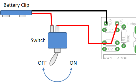
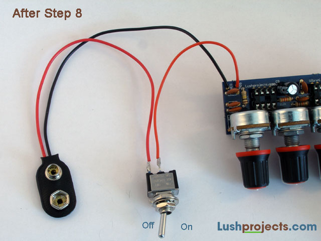
Build Step 8 - Connect the Battery Clip and Switch
To complete this step you will need the battery
clip, red
wire and switch. Take the battery clip and solder the red wire from the
clip to
one tag on the switch (use the same technique as you did for soldering
to the
speaker in Step 7). Conventionally in electronics red wiring is used to
show
the positive voltage and black wiring is used to show the negative
voltage.
Strip the ends of the red wire
and solder
one end to the other tag on the switch.
In the corner of the circuit board you will find
two holes
labelled “POS” and “NEG”. Connect the other end of the red wire from
the switch
to the “POS” terminal and the end of the black wire coming from the
battery
clip to the “NEG” terminal (use the same technique as soldering the
speaker
leads to the circuit board in Step 7).
Step 7