
Note the Vibrati Punk Console kits are no longer available - these pages are kept for reference and interest. You can find the schematics and source code in these documents, but the PCB designs are not currently public.
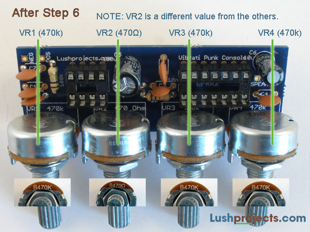
Build Step 6 - Add the Variable Resistors
There are four variable resistors that control the
sound of
the Vibrati Punk Console. These are soldered in a row on one edge of
the
circuit board so they can be mounted on a control panel if desired.
There are
two different values of variable resistor. The value is labelled in
text on the
case.
Identify the resistors as shown:
|
Variable
Resistor |
Value |
Markings |
|
VR1, VR3 and VR4 |
470k Ohm |
“470k” or “470kΩ” |
|
VR2 |
470 Ohm |
“470” or “470R”
or “470Ω” |
Put the variable resistors through from the
component side
of the board and solder the pins on the back. The control shafts for
the
variable resistors should face away from the board. The knobs provided
will
push-fit on to the variable resistor shafts.
Congratulations – you’ve now finished all the key
components
on the board. You now just need to mount the speaker, battery connector
and
power switch which connect to the board externally.
Step 5