-
PCB Layout Tools – I am a KiCAD fan
Posted on September 24th, 2013 No commentsFrom the postbag:
Was thinking about a project building front panels for various DIY synth projects out of PCB material and mounting all the control components (pots, switches) on the PCB itself like on the Lush (eliminating most of the point to point wiring). What PCB design package do you use and how difficult was it to learn?
Tom
Dear Tom,
As I’ve said elsewhere I hate point-to-point wiring so I made it a feature of LushOne to have all the components mounted on the board. I had previously used Eagle but the LushOne the board was too big for the low-cost edition. In any case, I like to use open source software when I can even though a lot of it is not that user-friendly. The LushOne was the 1st project I laid out in KiCAD and I’ve actually found it a really effective design tool.
Like all CAD systems it has a bit of a learning curve, but generally I’ve found it easier to use than Eagle. It’s not as powerful as Eagle and lacks the scripting capabilities but it is perfectly adequate for my projects.
The worst part of KiCAD is the Gerber viewer. I tend to use the online Gerber viewers like the one at OSHPark.
-
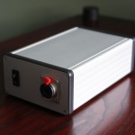
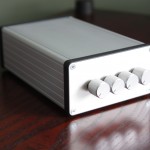
Could be the smartest Vibrati Punk Console ever
Posted on May 16th, 2013 No commentsLovely work from David Mead encasing his Vibrati Punk Console. It looks like a very smart and very expensive piece of Hi Fi. He says that it is his first project. Great job!
-
-
LushOne Contour Prototype – Adding ADSR envelopes and ring modulation
Posted on September 20th, 2012 No comments
The LushOne was designed to be the base module for a more extensive modular synthesizer system. Over the last few months I’ve been working hard on the second module – the LushOne Contour. The first batch of protoype boards arrived last week and apart from a couple of stupid mistakes they seem really cool. The Contour adds the following capabilities:
- Envelope generator with full Attack/Decay/Sustain/Release (ADSR) control
- Voltage controlled amplifier to shape the note volume from the ADSR (or other control) output
- Ring Modulator for wacky sounds
- Signal break in or out to a phono connector
- Extra low frequency oscillator

The ADSR envelope and VCA create much more natural sounding notes with proper sound contours.
The ring modulator meanwhile creates lots of ringing, atonal and percussive sounds.
Hope to get the LushOne Contour in production and available to buy soon. -
LM13700 OTA – The missing forumla
Posted on August 15th, 2012 No commentsIf you do anything with analogue syths you quickly run in to the Operational Transconductance Amplifier (OTA) as a key component. These are amps whose current output depends on the voltage difference at the inputs and a control current that scales the gain. They are used for voltage controlled filters, voltage controlled amplifiers and oscillators. The subject of OTAs has a complicated and initially frightening set of assumptions, concepts and implicit ideas around it and getting a handle on the whole thing takes some effort. This blog post isn’t a general introduction to OTAs but it talks about how I solved a particular problem in my understanding and spotted a mistake in one of the common write-ups.
Digital techniques are replacing a lot of OTA applications and OTA chips are being discontinued like there is no tomorrow. One that is still available (and I use in the LushOne) is the venerable LM13700. While designing a voltage controlled amplifier and ring-modulator for the LushOne I found I needed to get a deeper understanding of the LM13700 than I had had before and started to explore the behaviour of the chip in detail. In particular I wanted to be able to predict the gain when the linearization diodes are in use.
The obvious place to turn is the LM13700 data sheet. This is kind-of famous because the designers tried to pack a lot of information and examples of their great new device in but the commercial pressures meant the datasheet needed to be kept short. It is therefore rather compactly written and understanding the example circuits is often an exercise for the reader. Initially though the case I was interested in seemed simple enough. The data sheet provides a nice equation with the glowing claim “no approximations have been made”.

What do all the terms mean? IABC is the amp bias current (pin 1 or 16). ID is the diode bias current (pin 2 or 15). What is IS though? Fortunately Figure 1 of the data sheet tries to tell you – IS is the current being injected in to one input of the amplifier while the other input is grounded. So it all looks nice and simple – except that on the bench the gain I got was about half what I would have expected from this forumulat. In other words the figure of 2 in the numerator seems wrong! Getting to the bottom of this involved a lot of head-scratching and measuring and simulation. Once there the answer is obvious, but at the time it was a big mystery.

I should say at this point that the LM13700 datasheet is absolutely technically correct, but it is rather easy to misunderstand if you don’t apply your brain sufficiently. The problem lies in the interpretation of IS in a real configuration. Normal configuration (and I think any practical use of the LM13700) doesn’t use current sources to set IS and ID/2 at the input as shown above. You use resistors. This makes the real configuration look more like the figure below which is copied out of a couple of magazine articles by Ray Marston that crib heavily from the data sheet. Unfortunately though he has usefully shown the practical configuration the current flows shown are absolutely wrong for this set-up.

The problem is translating the datasheet theoretical diagram in to the real implementation. An easy thing is to assume (as shown above) that IS is the current through R4 and the rest of the datasheet assumptions then apply leading to IOUT = 2 . IS . IABC / ID. What this overlooks is the role of the ID/2 current sink shown in the datasheet figure. In the data sheet the IS and ID/2 current sources/sinks together force the current in one leg to be ID/2 – IS and this forces the other leg to be ID/2 + IS. When you use a resistor to ground instead of a current sink then the relationship between the current in the two legs changes and the system gain becomes different as well.

Simulation and also careful consideration reveals then when you input a current in one leg in the practical system the effect is to increase the current flowing through both R1 and R2. Let’s try and do some analysis – I have used a new term IG for the input current to remove confusion with IS. I’ve also neglected any currents going in to the base of the transistors that form the differential amplifier. The voltages at the cathode (pointy end) of the two diodes (V1, V2) are approximately equal because a forward biased diode is a rough voltage reference – which means the currents IR1 and IR2 are also approximately equal.
ID1 + ID2 = ID
and ID2 = IR2
and ID1 + IG = IR1
Therefore if IR1 ≈ IR2:
ID2 ≈ ID1 + IG
Or (ID2 – ID1) ≈ IG
and ID1 ≈ ID/2 – IG/2
and ID2 ≈ ID/2 + IG/2
So compared to the Marston diagram the difference in the currents is half that predicted. Assuming the ratio ID1 to ID2 drives the output this makes the system gain:

which fits with roughly the measured results.
So, now do we have the missing equation for the LM13700 gain in its most common configuration? Well the answer is (very) “roughly”! If you are on the ball you will notice that if V1 really was the same as V2 then the differential amplifier would have no differential input and therefore zero output. It is precisely the difference in V1 and V2 that drives the output! Hence the assumption that V1≈ V2 the above derivation is dodgy. All I can say is that from experience and simulation it seems to be OK as long as IG << ID and R1 and R2 are reasonably large. With R1=R2=470 Ohms then the simulated gain is about 12% less than the above formula would suggest. For my applications I always have adjustments to allow the user to set the gain and therefore the above formula is good enough to set the component vaues to give the desired range of adjustment. I suspect if you wrote out the maths properly and did the function expansions you could justify the approximations better and understand exactly how factors like the value of R1 and R2 impact the gain.
From deconstructing what went wrong and fixing my (and it seems others’) faulty assumptions I learnt an incredible amount about the LM13700 operation. What’s the moral here?
1) If a data sheet is obviously written with precision then read it with precision.
2) If there is an interpretation trap then you may not be the only person to fall in to it!
Update (2017)
You can now see the two circuits (datasheet version and “typical” configuration) simulated in the browser here:
http://lushprojects.com/circuitjs/circuitjs.html?startCircuit=ota-gain.txt
-
Hybrid, patchable synthesizer
Posted on March 14th, 2012 No commentsI made this video a while back but it’s taken me ages to get around to posting it on the blog.
I’ve wanted a modular synth for ages but I could never justify the cost so I decided to make one that was “cheap as chips” (silicon chips of course). This is the perf-board prototype. It makes a great range of sounds.
More on this very soon.
-
Experimental Korg Monotron Filter (Part 2)
Posted on November 8th, 2011 No commentsEver since Samuel Freeman produced some great sounds playing his Vibrati Punk Console through a Korg Monotron at Dorkcamp I’ve been mildly obsessed with the Monotron circuit. The heart of the Monotron is the Voltage Controlled Filter (VCF) which is based on Korg’s classic design for the MS20 synth. Korg did DIYers a great favour by publishing the Monotron schematic back in 2010.
To try and understand the filter better I built a VCF “clone” on breadboard and then moved it over on to a perf-board. It has been an experience that is at times fascinating and at times frustrating. Internally the VCF uses some very low signal levels which are then boosted with a monster-gain amp. Net effect of this is to make the circuit very sensitive to component changes and environmental factors. I had to substitute for the transistors and the FET in the original design and this threw out a lot of other things. I found that swapping the three transistors around could make the difference between the circuit self-resonating or not. It seems unlikely that Korg will be selecting individual components on their Monotron production line so I don’t know how they manage to get good enough consistency in their builds.
The final working model is interesting. Perhaps rather noisier and not as musical as the original, but the sound is certainly striking.
For those that like the details here are the mods compared to the drawn Monotron schematic (component designations are Korg’s):
- Q12-Q14 are 2N3904. As noted above the order of selection of these can make a big difference.
- F3 is J112. As this has a different Vgs from the original I then had to add an AC coupling via a 1uF capacitor to the op-amp with the input DC linked to the voltage reference via a 100k resistor.
- D1 and D2 are red LEDs to increase the clipping voltage on the output.
- R60 is 680k to make sure the circuit will self-resonate
- R73 is 680R to reduce cross-over distortion in the Op-amps output. I think the way that Korg bias the op-amp the output doesn’t go in to the cross-over zone so this wasn’t an issue for them. Because I changed the biasing it becomes an issue for me.
-
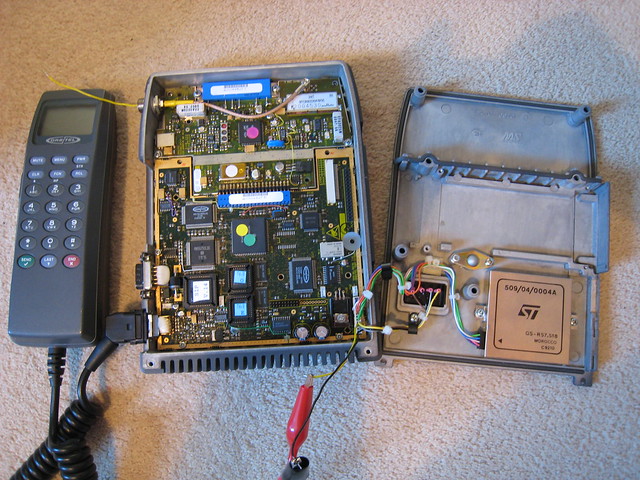
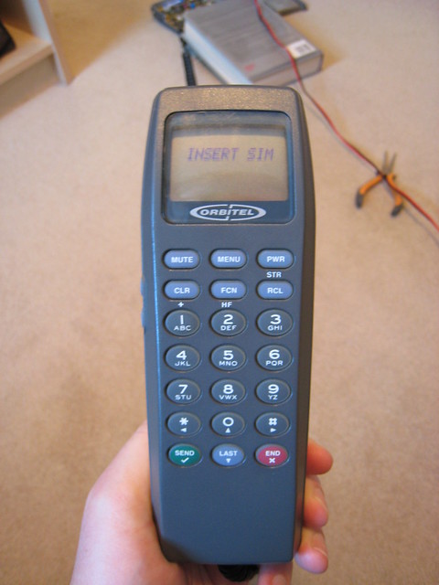
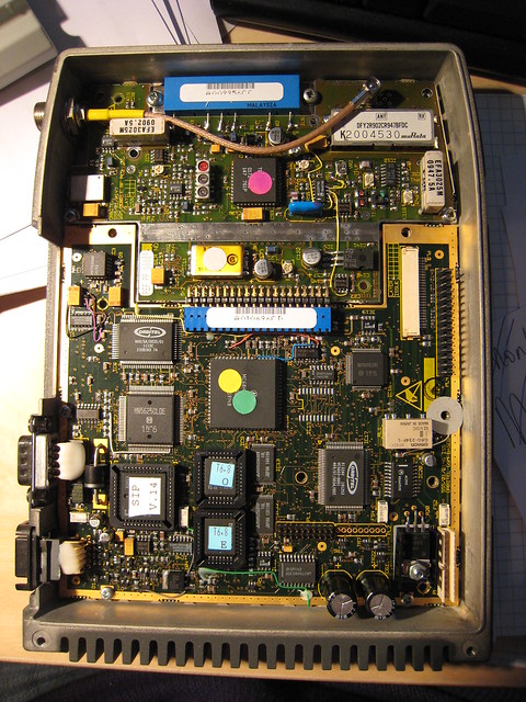
Oldest working mobile?
Posted on October 19th, 2011 No commentsFriends of mine are planning a “who has the oldest working mobile” event. I have an Orbitel 863 from about
1994[Edit:] 1992? which I reckon could be a winner. With a bit of searching I found a post in German that gave correct pinouts for the battery. In a quick test the mobile powers up OK without a SIM. Given it is a somewhat powerful radio transmitter and it is missing its antenna I haven’t dared try anything else yet. Anyway, here are some photos.Edit: Another source on the web dates this mobile to 1994 without giving any evidence. From the design and what I know of its history I would say it was a very early GSM mobile and 1994 feels a bit late. There are various date codes visible on the boards and body castings. The latest date code I can see is “21 92” (ie week 21, 1992) on the main circuit board. Therefore I believe that this is a phone from 1992.
-
Vibrati Punk Console with optical control – New video
Posted on July 20th, 2011 No comments -
Lushprojects.com will be at Brighton Mini Maker Faire
Posted on July 18th, 2011 No comments We are going off to the seaside in September. Lushprojects.com will be a Brighton Mini Maker Faire with circuit bent electronics to play with and a chance to buy and build the Vibrati Punk Console. Hope to see you there.
 -
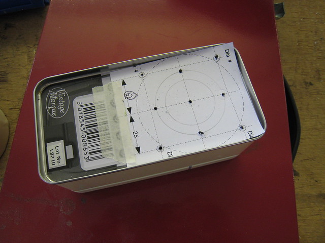
Vibrati Punk Console – second boxed version
Posted on July 12th, 2011 No commentsJust made this at Nottingham Hackspace using a Vibrati Punk Console that Clare soldered and a mini tin box for vodka that we got at Christmas. I rather like it.
Used my own drilling guide to make it.