

-
Networking CATWatch
Posted on December 30th, 2020 No comments(or an overkill solution to tracking the movements of a cat)
I don’t mind cats, but we have one Top Cat (subsequently TC) living locally who thinks he (or she) is the boss of everything. After one too many cat shits and dead birds in our back garden I decided that TC was no longer welcome and was going to be excluded.
Early steps were very simple – filling in the gap under the gate prevented easy access until TC found new ways over the gate and fences. I then decided a more through approach was needed. I installed a Pi Zero W with a night vision camera module (1) running motion project software so I could see whether TC was coming in the garden and perhaps how it was getting in. It works OK with the caveat that the Motion Project software is pretty simplistic in its approach to doing movement detection and even after tuning the parameters I get a lot of false positives. It is a little painful to manually check the output, but that’s OK.
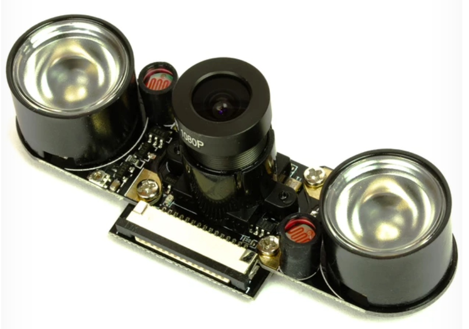
Night Vision Camera Module (before I removed the IR LEDs) I also put in an ultrasonic cat deterrent on the edge of the lawn. This is a passive infra-red (PIR) motion detector linked to an ultrasonic sounder that is supposed to scare cats. There are lots for sale – I used the RSPB CATWatch. It is a battery powered device where motion detected by the PIR triggers an ultrasonic alarm that sounds at about 20kHz for a few seconds. Interestingly, the alarm doesn’t just play a single tone, it varies the tones during the alarm period, presumably to prevent cats getting habituated to the sound.
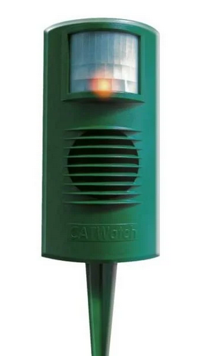
RSPB CATWatch After that we didn’t see TC in the garden for quite a while. We thought the CATWatch probably was scaring it off, though we never caught it in the act. But, one day the camera caught TC strolling around the edge of the lawn, just out of range of the CATWatch PIR detector. Knowing TC was still coming in the garden I followed the example of my neighbour and put cat deterrent spikes around the fence tops, and (so far) we haven’t seen TC again.
But, here is the problem, how do I know TC isn’t coming in any more? The camera sees a lot, but it also misses a lot. Despite its name, the CATWatch doesn’t really watch cats, it just scares them off. In fact you have no way of knowing how often it has been triggered. I wanted a CATWatch extension to log when it was triggering, and ideally to trigger the camera to record too. So, there are two problems:
- How to cause a trigger for the CATWatch to activate an external circuit, and
- How to connect the CATWatch to the Pi Zero without running wires everywhere?
I started thinking about how I could get a wireless signal from the CATWatch to the Pi. My requirements were:
- Simplicity
- Keep the CATWatch battery powered without significant reduction in battery life
- Fast reaction so that the camera will be activated while the cat is still in the vicinity.
The obvious option was WiFi, but keeping that running long-term on a battery is problematic. If you disconnect from the WiFi to save power then reconnecting will add a delay which might not meet the “fast reaction” requirement.
BLE was another option, but the thought of working out the right stack of hardware, libraries, low power modes etc. to make it work made my eye twitch. Modern systems are amazing, but, unless you already know the ecosystem and tools, understanding enough to use it effectively can be a massive PIA.
I realised what I wanted was something very simple, almost primitive, that I could just hook up at each end to send an on/off binary signal. The technology that seemed to fit that best was 433MHz radio remote controls used for garage doors and similar things. I bought a set of 5 key fob transmitters and a 2 channel relay board receiver on ebay. The plan was to put a transistor across one button on the transmitter to send and to remove the relay to get an open collector transistor output on the receiver.
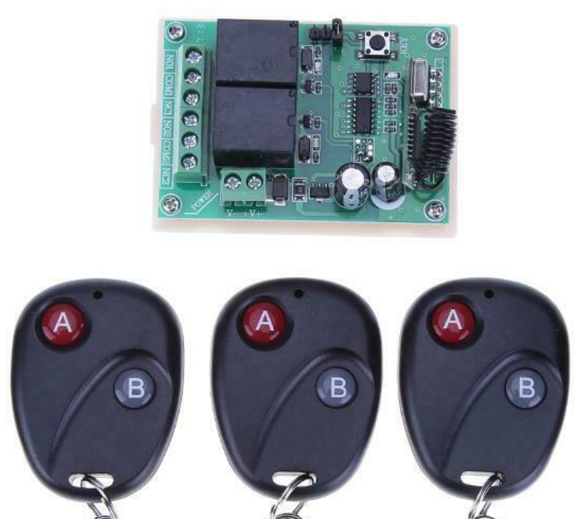
433MHz Receiver Board and Some of the Key Fob Transmitters The receiver board is rated for 12V input, though it worked down to 9V. What I really wanted was for it to be powered off 5V from the Pi. Looking more closely I found, as I expected, that the only part of the circuit that used the 12V was the relay coil. The rest ran on 5V from an internal regulator. I removed the relay and bypassed the power regulation on the board to produce a 433MHz receiver that ran on 5V and could (using an open collector output that originally drove the relay) link to a 3.3V GPIO input on the Pi.
The transmitter fob was very simple – the two buttons just connect a wire to the positive end of the 12V internal battery when pressed. So the only unexpected problem is that I would need to implement a high side switch, rather than a low side switch as I was expecting.
Getting the CATWatch to activate an external circuit would probably be easy, but for one problem: all the electronics are potted in resin except for the power-in and the wires going to the ultrasonic transducer. So, there is no obvious binary “alarm” signal accessible to drive an external circuit. You could trigger based on the ultrasonic output, but I thought it would be easier to use the power input and detect the very marked increase in power consumption that occurs when the alarm is turned on. I put a 15 Ohm shunt in the power line driving a PNP transistor to do the high-side switching for the transmitter (as shown in this simulation). I decided to keep the two circuits on their original batteries, so, to do the high-side switching, these two batteries connected positive to positive as shown.
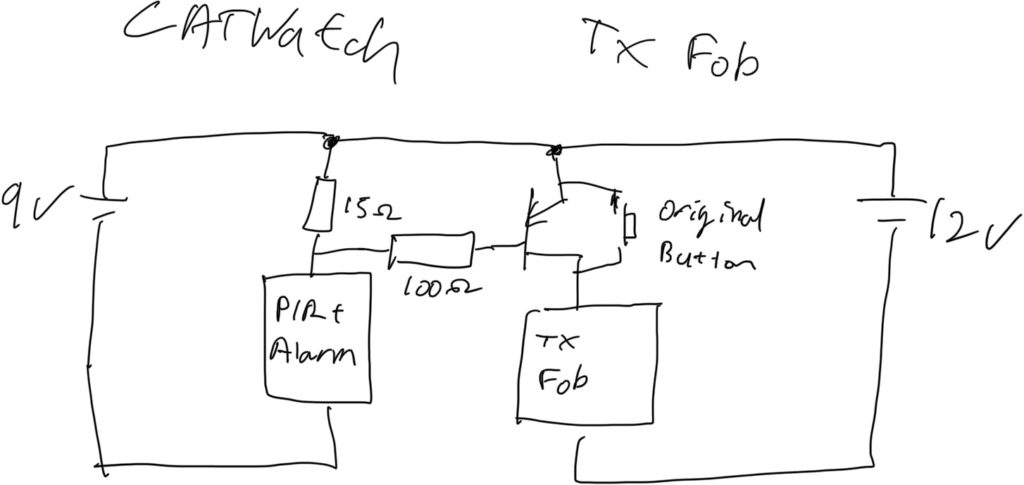
Block Diagram of Connecting CATWatch to the Key Fob Transmitter As always, I hit a snag at the last moment. There was enough space in the CATWatch to include the transmitter fob in the unmodified case, but I found that when the case was closed the alarm wouldn’t turn-off once it had been activated. My suspicion is that the transmitter interferes with some high-Z input that is being driven by the PIR and the circuit keeps thinking it is detecting new motion. So, I 3D printed a “back-pack” that contains the fob circuit and can be attached to the back of the CATWatch away from its electronics. That worked fine and also makes it easier to change the fob battery if needed.
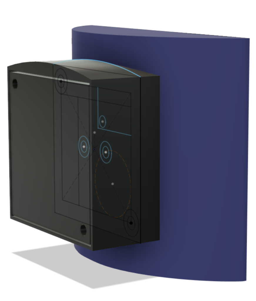
Design for the Back-Pack to Hold the Key Fob On the camera side I also got the 3D printer working to make a case to contain the Pi, camera and 433MHz receiver. This is attached to a sheet metal bracket (made from an old baking tray) which allows the camera to be hung from our windows and the window to still close. I wrote a small Python script that monitors the GPIO connected to the 433MHz receiver and logs any events. It also uses the Motion HTTP API to trigger Motion to record video if the CATWatch is activated.
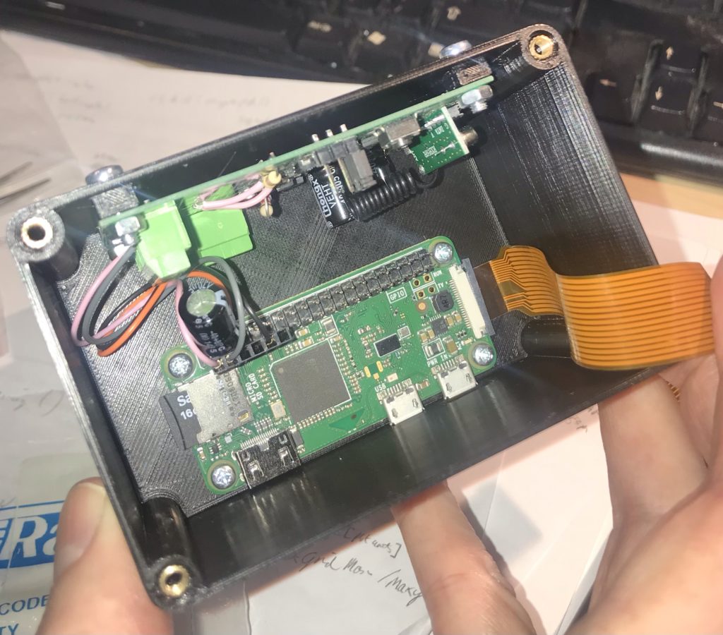
Camera Case – Pi Zero in bottom, Receiver Board on Size, Ribbon Goes to Camera in Lid 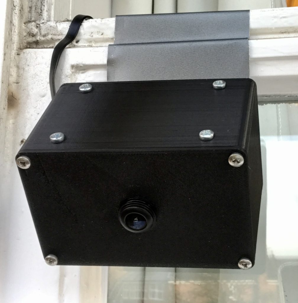
Camera, Pi and Reciver Mounted on Window I am getting about 8 meters line of sight operational range on the 433MHz signal which is good enough for this application. Since it all went live the only animal to trigger the CATWatch was a squirrel which wandered right in front of it. So, touch wood, it seems that the project to secure the garden against TC is working. Come the spring, I hope the nesting birds appreciate the effort. We wait for TC’s next move!
Of course this project is completely and ridiculously overkill, but the new parts were pretty cheap and it was fun to build. It’s nice to do some back to basics local networking and to have a completely self-contained solution that doesn’t depend on some dubious cloud-based subscription like almost all commercial home automation services do. I can see that there are a lot of other potential applications for simple 433MHz technology which I might want to explore.
(1) A couple of notes on the night vision camera. Firstly, the included IR LEDs for night lighting are pretty feeble. They might light about 2-3 meters, but not further than that. I ended up removing them as they weren’t lighting anything useful when the camera was on an upstairs window. They also cause false positives when it rains due to reflection from raindrops.
The IR LED modules are self-contained (including a light sensor to turn them on) so they could possibly be repurposed as a light source to be used away from the camera. Without IR illumination the camera doesn’t really see in the dark, so I would probably have go for a normal (non-IR) camera if doing this again.
The camera comes with a choice of lenses. Due to breaking one camera I ended up with both lens options. One thing to note is that the lens needs to match the plastic base that it screws in to if it is going to focus properly. If you want to swap lenses on a board you can’t just move the lens over, you also need to move the base.