Note the Vibrati Punk Console kits are no longer available - these pages are kept for reference and interest. You can find the schematics and source code in these documents, but the PCB designs are not currently public.
Use

Here are some tips on the range of sounds available from the Vibrati Punk Console. The circuit splits in to two parts - the basic Atari Punk Console is controlled by VR3 ("Base Frequency") and VR4 ("Divider"). The Low Frequency Oscillator (LFO) is controlled by VR1 ("LFO Frequency") and VR2 ("Depth").
To get going turn VR2 "Depth" all the way to the left. This turns the LFO off and the sound is just like an Atari Punk Console. VR3 "Base Frequency" sets the starting note in the circuit. This is also the highest note that the Vibrati Punk Console plays. VR4 "Divider" controls the pulse shape (which varies the harmonic content) and the frequency division applied to the base. These two controls interact to give a tone sequence effect.
The effect of the LFO depends a lot on the settings of VR3 and VR4. A good setting to start with is to set VR3 "Base Frequency" and VR1 "LFO Frequency" to the centre and VR4 "divider" to the 3/4 mark. Now vary the VR2 "Depth" control and you'll hear the impact of the LFO. From here you can play around with all the controls. If you set VR4 "divider" too low you may find that the LFO isn't very audible.
Below you can find some technical information about the Vibrati Punk Console including a drilling guide to mount in a case. I've also suggested some modifications you could try. The circuit is very open to many types of changes and I would really like to hear from builders about their enhancements and any photos/videos of your kit in action.
Circuit Diagram
The circuit diagram for the Vibrati Punk Console is below. One day I'll write a proper description, but here are the highlights:The circuit consists of two parts. The first part is an NE555 IC wired as an astable oscillator that acts as the LFO. The second part is the Atari Punk Console circuit. The modulation takes place by using the modulation input to the base frequency of the Atari Punk Console from the LFO.

Line-Out Modification
Difficulty rating: ModerateThe VPC circuit is very open to mods and bends. I'll add more here as people suggest them. To start with I've had a request by @GuerillaBass to add a line-out.
To add the line-out you will need two more resistors (10kΩ and 1kΩ) and a suitable jack socket. Connect them as shown below. In the circuit below connecting line-out jack won't disconnect the speaker. Most jack sockets have a built-in switch that you can use to automatically disconnect the speaker if you want.
NOTE: As with connecting any new device to a mixer take great care. Before connecting turn everything off and set the levels right down. Once connected turn power on and very cautiously raise the levels. I very strongly recommend you use a battery to power the Vibrati Punk Console if you connect to a mixer. If you do use a mains adapter then ensure the "ring" connection on the jack socket is connected to the left-hand "speaker" output on the circuit board (above the letter "p" in the label). This is the 0V output. With a battery this isn't critical.
Some users have reported that the line out level is a bit high with this circuit. If you find this problem try reducing the value of the 1kΩ resistor. 680Ω or 470Ω would be reasonable values to try.

Touch Control Modification
Difficulty rating: EasyProbing a circuit with a wet finger can sometimes yield interesting results and this has become a staple technique of the circuit bending community. Of course this should only be done on low-voltage battery powered circuits like the Vibrati Punk Console. The VPC circuit works well under touch control. To get started turn VR1, VR2 and VR3 fully anti-clockwise. Turn VR4 up to about 3/4rs of the way clockwise. Now try touching the circuit with a wet finger on the back of VR3 and VR4 between the variable resistor contacts shown. You should find your finger will modulate the sound.

Why does this work? Your body (particularly if you make the skin damp) is a conductor of electricity. In fact the resistance is in the same range as that produced by the variable resistors VR1, VR3 and VR4. When you touch across the variable resistor terminals the resistance of your body appears in parallel to the resistance of the variable resistor which produces a net reduction in the resistance.
If you turn VR2 up to about half-way you should also find there is a touch-point on the bottom VR1 also.
Circuit-benders often bring touch points out as metal studs that act as body contacts on the outside of the case. If you want to make body contacts for the VPC then solder wires to each of the contacts at the touch point and then attach the other end to a bolt going through a plastic case. To solder a wire to the back of the board start by stripping 2-3mm of insulation from the end of the wire. Melt a little solder on the soldering iron and then "tin" the wire end by dipping the wire in the melted solder ball. Now use the soldering iron the melt the joint on the circuit board and put the tinned wire end in to the melted solder. Remove the iron and wait for the joint to solidify.
Pulse Output Modification
Difficulty rating: Fairly easyThough the sound of the Vibrati Punk Console is delicious it may be a little bit too much to play continuously in most situations. Therefore you may want to modify the circuit to allow the sound to be pulsed on using a push-button. This can be done by adding a push-button in parallel to the power switch but as it takes a moment for the sound to stabilize after the circuit is switched on you may prefer to add a push button control in the output of the circuit.
To add a push-button to the output follow the diagram below. I've included a switch so that you can either have continuous or pulsed operation. If you are in pulsed mode don't forget to switch the circuit off when not in use as it will still be consuming power even though it isn't making any sound.

Optical Control Modification
Difficulty rating: somewhat fiddly!This modification changes the Vibrati Punk Console to use a light-sensitive input to augment the VR3 function. You will need a 100nF capacitor (normally labeled "104") and a photocell (also known as a "light dependent resistor"). These two components need to be attached to the track-side of the board. The capacitor can be directly mounted on the same pads as C3. Use a similar technique to that described for mounting wires in the "touch control modification" to make the connection to the extra capacitor. The photocell can be connected directly on the board using the active pads on VR3 or it can be connected via wires and brought out on to the outside of a case.
To make connections to the back of the board start by putting a generous amount of solder on the joint you want to connect to. If you are connecting a wire then strip a tiny amount (2-3mm) and tin the wire by covering it with a little solder melted on the end of the iron. Use the soldering iron to melt the joint on the circuit board and insert the wires you wish to connect in to the molten solder blob. Withdraw the soldering iron while leaving the wiring in place until the solder sets again.
Once you've connected the additional components turn VR3 fully anti-clockwise and then use your hand to vary the amount of shadow falling on the photocell to change the tone of the instrument.

YouTube video of a Vibrati Punk Console with the optical control modification.
Optical Control Modification with Switch
Difficulty rating: HardishThis is a variation of the above modification but with the addition of a switch to move between opto and normal control. It has been requested by a few people. I haven't tested it but it should work. Because you need to switch two components in and out of the circuit you will need a double pole switch.
In opto mode (switch position labelled "on") you will probably also want to turn VR3 fully anti-clockwise.

Gate Input Modification
Difficulty rating: somewhat fiddly!This modification allows the output of the Vibrati Punk Console to be switched on and off by an external gate signal. This means that the module can be integrated with some types of sequencer or other modular components. The gate signal is of the "V-Signal" type ie a voltage of between 1 and 9V will turn the output on. A low voltage will turn the output off.
The modification requires cutting the track to pin 4 of IC2. This is the "reset" pin and by connecting this pin to an external input we can stop the master oscillator in the circuit. Cut the track very carefully with a sharp knife and make sure that no connection exists across the cut. I normally make two very close parallel cuts and then "dig out" the gap between the cuts with the tip of the knife.

You now need to connect a "pull up resistor" and leads to the gate input to the track-side of the circuit board. The "pull up" resistor connects the reset input to the positive supply via a resistor. This keeps the input high when there is no external connection and means the circuit will work as normal. When there is an external connection the external signal will dominate over the pull up resistor.
For advice on soldering to the back of the board then see the "optical control modification" section.

Modulation Input Modification
Difficulty rating: Tricky and experimentalThis is an experimental modification for those that want to try something slightly off-piste. It provides an external input that can be used to modulate the Vibrati Punk Console circuit instead of the internal Low Frequency Oscillator. I don't guarantee this modification will work but it did for me in tests. The external input is AC coupled therefore it needs to be connected to a varying signal like an audio playback or oscillator output rather than a DC control voltage.
To do this modification you need to cut the track between VR2 and C5. For advice on cutting the track see the "gate input modification" section. The tracks are very close in this part of the circuit board so take care not to damage adjacent tracks.

Once you have cut the track connect the external input as shown below. For advice on soldering to the back of the board then see the "optical control modification" section. Once the additional circuitry is added you can switch between external and internal modulation. For internal modulation the circuit will work as normal. For external modulation the LFO controlled by VR1 and VR2 will no longer operate and the external input will provide a modulation effect.

Case Mounting
Quite a few people like their Vibrati Punk Console so much they want to mount it in a case for regular use.The circuit board can be held in place just by mounting the variable resistors (VR1 - VR4) through suitably spaced holes. Two holes are needed for each variable resistor as there is a small locating tag on the left of the main shaft. The on/off switch can be mounted in its own hole.
To mount the speaker I suggest you drill holes in four places round the edge of the speaker. Pass bolts through these holes and secure the speaker with flat washers and nuts. See the diagram for sizing.
Suggested Case
The suggested case for the project is a 100x75x40mm plastic case type EN002 from bitsbox.co.uk. Alternatively Maplin part number LH21X looks almost identical (though I haven't checked the Maplin case).In the suggested case the circuit board and controls are mounted in the top (lid) and the battery and speaker in the bottom of the case. You may need longer wires than those that came with the kit to connect up the speaker OK.
Drill the case according to the diagrams below. They are also available as a PDF file that you can print actual size (do not use "Scale to fit paper") and tape to the case to use as a drilling template.
Drilling tips: Before drilling or marking the case support the panel being worked on from behind with a wood off-cut. Mark the centre of the holes with a sharp-point (plastic) or a centre punch (metal cases). Drill a small pilot hole first and then enlarge to the required size.
Use 4mm bolts through the corner holes to hold the speaker. Put flat washers and nuts behind the speaker to hold in place.
Mount the battery on its side on top edge of the bottom part of the case using a generous piece of "blutack" or similar to hold it in place.

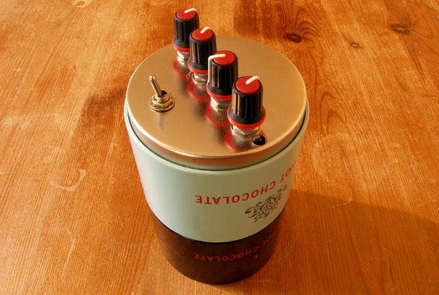
Vibrati Punk Console in the suggested case. This version has both the line-out and the pulsed output modification.


Other Cases
For drilling other cases here is a PDF file with the mounting plans drawn full size. Print actual size (do not "Scale to fit paper") to use as a marking template.
Thanks
Special thanks to the crew at Nottingham Hackspace for their support for this project and particularly Jake Howe for design of the project graphics.