Video bending - 2009 and 2010
Since doing the circuit bending course where I built the Honkatron I've wanted to try some video circuit bending. There's a lot less circuit bent video stuff around than there is audio, so I reckon it would be easier to do something that stands out. Bending video circuits is quite a lot more demanding than audio circuits. You have to preserve the structure of the video signal quite carefully or else displays can't process it properly and won't produce a picture.
For about a month I went mad on eBay buying any cheap and interesting looking old video mixers. Classic in-demand mixers like the Panasonic WJ-MX12 are expensive. Simpler models (particularly those without the ability to sync multiple inputs) can be got quite cheap though. Often the shipping costs more than the item. Of course on eBay there is always somebody who is going to try and sell something for far more than it's worth, so if you fancy buying something yourself watch the prices and don't be pushed in to buying too quickly.
For more information about my technical approach to video circuit bending then see this blog post.
With lots of mixers in stock it's time to start doing some circuit bending...
| GSE VEP-2 This was the second GSE mixer I bent. I had so much fun with the first one (see below) that I was determined to try another. They aren't easy to find in the UK so an Austrian guy helped me buy one off German eBay. I was expecting a clone of the one I already had (after all it looked identical) but when it arrived I discovered it was a different mixer with different functions housed in the same case! The VEP-2 looks like a cost-reduced version of the AVEP-2S. Gone are all the fancy Phillips video ICs and RGB processing. Instead we have much simpler (mostly discreet) circuits working on the composite video signal. By this stage my Camlink Vision 400 was starting to become unreliable so I decided to try and clone the most interesting functions on the VEP-2. Without any big ICs to home in on it required careful tracing to work out how the circuit operated and where the key components were. After a lot of heartache (and rereading a lot of analog transistor design notes) I came up with some interesting bends including a mega colour boost and a colour inversion. Decoding all the analog design made this a long build and with a deadline to meet I started to rush the final construction. This lead to a nasty moment - when the unit was almost complete I swapped my normal bench power supply for a "wall wart" adapter without checking the polarity. Disaster! I had just connected reverse-power on to the whole circuit. Nothing seemed to work any more. At that point I almost gave up, but I noticed with the bench power supply on that it drew no current which seemed odd. With further study I found a single PCB trace near the power connector had melted and saved the rest of the circuit from certain death. What a massive relief that was! Scores on the doors: Unmodified: 6/10 Bending potential: 7/10 |
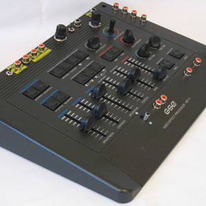 GSE VEP-2
 Prototype bends on
GSE VEP-2
 Testing GSE VEP-2
bends
|
| Panasonic
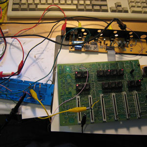
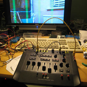
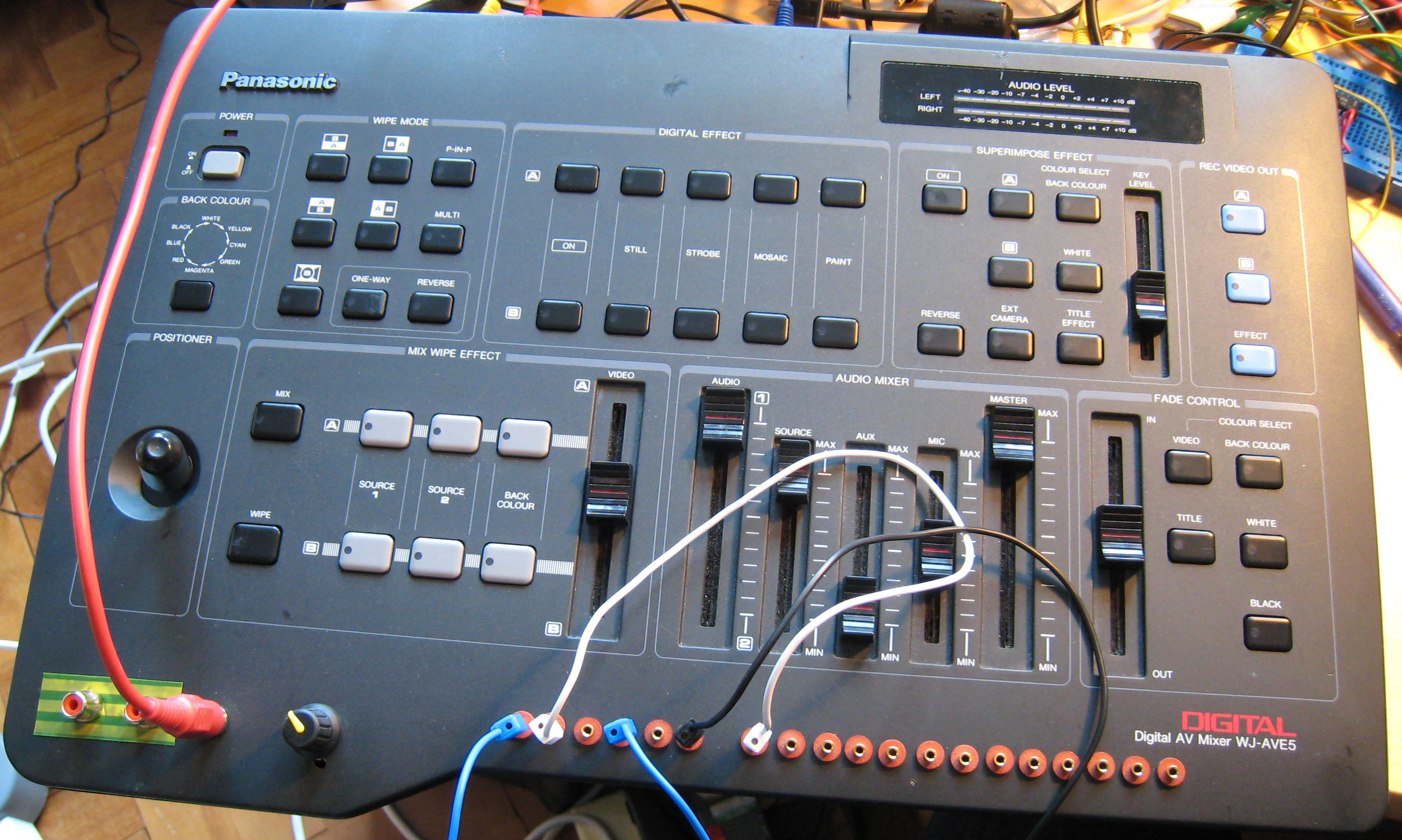
WJ-AVE5 The WJ-AVE5 is one of the classic range of digital video mixers made by Pansonic. Still lots around, but tend to get rather silly prices on eBay. Also easy to break if you aren't careful - not a bending platform for the faint hearted. Being naturally cautious I got a service manual from manuals-in-pdf.com before starting work on mine. The service manual isn't very very informative about device parameters but does have full circuit diagrams. The AVE5 sits at the end of my video mixing chain. It generates clean sync signals and therefore is good to drive the final output. It also provides nice clean fades so good to start and end shows. The AVE5's circuit is based around a pair of identical chips that drive the A and B busses. I started work using tips from Karl Klomp. His approach is to connect pins from the resistors to the right-hand side of the main chips to ground and other signals. It works well, but I found it easier to pick-up the same signals from the pads put in for unused memory chips. I decided only to bend the B-bus to leave the A-bus clean for normal operation. With a bit of poking in the manual I was able to find some interesting bends of my own too. On IC 224 (the long DIL IC under the B-bus main processor) you can pick up signals that drive the wipe-effects and the title-keying. These are both really exiciting for me as messing up keying effects is one thing I love to do. The other thing I learnt from the service manual (which is hardly mentioned in the user documentation) is that the mixer will sync it's output to the "Ext Camera" signal if you provide one. This is really useful to extract the key/wipe signals. I disconnected the termination resistor on this input so I could passively split a signal in to it without changing the levels. To bring the signals out the front I used 2mm sockets. The long leads mess up the normal operation a bit but not too badly. The final creation is a monster! In a good way of course. Scores on the doors: Unmodified: 8/10 Bending potential: 9/10 |
 Panasonic
WJ-AVE5
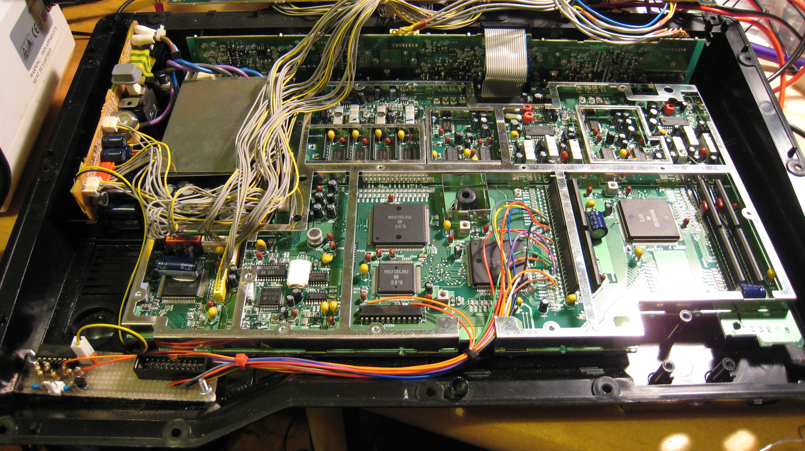 WJ-AVE5 circuit bent wiring on B-bus  WJ-AVE5 close up wiring to unused memory pads |
| CamLink
Vision 400 This was my first attempt at circuit bending a mixer. The mixer itself is a very horrible thing - anybody who tried to use it to edit their VHS tapes was not going to like the results very much. Its simple circuits and cheap-as-chips construction makes the video output dodgy to say the least. From the point of view of someone wanting to do a circuit bend though it's disadvantages suddenly become pluses as you can find all kinds of interesting features. I couldn't find any documentation for this mixer online, so I traced the most interesting parts of the circuit by hand. The bends are mostly pretty simple (well you got to start somewhere...). "Super boost" switches were added to the main controls giving really exaggerated output. Lots of points to extract or insert interesting signals were brought to phono sockets on the front panel. Internal control trimmers were also brought out to external controls. Lastly the ability to gate the signal from external sources was added. The final result is pretty good for a first attempt. Main issue is that it's sync isn't very robust. If you push the effects too hard the sync gets lost and the output will blank on the monitor. Scores on the doors: Unmodified: 4/10 (generous) Bending potential: 6/10 |
|
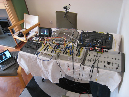
| GSE AVEP2S I bought this processor because it looked interesting and it had a joystick. How can anyone not be attracted to a video mixer with a joystick? It's a pretty obscure product from a defunct Germany company and there is virtually no information around that I could find. It's interesting because it pushes at the the limits of pre-digital equipment. There are a load of wipe patterns that are all created by complicated arrangements of analogue function generators and comparators. It does contain an 8 bit microcontroller, but as far as I can tell this is only there to control the function selector buttons. Overall it goes to some crazy lengths to perform its functions. Lots of big special purpose Phillips video chips. Another odd feature of the device is that it has more hand-mods on its circuit board than any production equipment I have ever seen. It must have been a nightmare to manufacture and support - no surprise that the company that made it isn't around any more. The good news is that all these complicate circuits makes it extremely bendable. I spent months tracing some of the main circuits and finding ways to change them. Almost everything I looked at seemed to invite changes. Brining all the changes together required me to add a second box in order to give enough space for all the mods and controls. This contains one of the two original circuit boards as well as my own circuits. The original case contains the other board and is linked by a single ribbon-cable umbilical which was used in the original design. The final version has 23 new switches, 18 pots and 33 connectors added. Phew - that's a lot of wiring! This allows the performer to make crazy modifications to the wipe patterns and extract or insert all kinds of intermediate signals. One feature that works really well is the ability to swap the colour channels around or to insert a signal on just one colour channel while keeping the others set as the original. This mixer regenerates the sync pulses internally instead of just passing them through like the CamLink box does. This means its much more tolerant of extreme bending without destroying the sync on the output picture. If you turn everything up to "11" though it can still overload the circuits. I could probably spend many more weeks squeezing all the possible bends out of this box, but eventually I decided it was time to move on. The video below is as recorded live and unedited. I did put the patches in first though. The video sources are from the two cameras you can see in the photo on the right. The effects are all from the the GSE AVEP-2S box except for the titles which are from an unmodified Camlink Vision 500 titler. The music (used with permission) is the from the excellent Krautpop EP by Minke. Was on YouTube, but the quality was poor. Much better on Vimeo (but slower to load). Scores on the doors: Unmodified: 6/10 Bending potential: 8/10 |
 GSE
AVEP-2S circuit bent control unit
 Expansion box for extra connectors and controls  Wiring for expansion box  GSE AVEP-2S with cameras for recording |
|
|
|
| Down the bar Down The Bar is not where I should be, but the name of this project. Unlike the previous projects Down The Bar is built from the ground up. It does need external support from the circuit bent video generators to be useful though. The project was inpired by the VS001. I wanted to do something similar with a composite signal (what all my mixers work on) rather than the VGA used in the original project. In the end I used the ability to separate the sync and insert video that came from the GSC bending described above. Down The Bar can add horizontal or vertical bars to the video. These can then be modulated by inputs like sound or indeed the video signal itself. There are two identical generators each of which is just made from two CMOS monostables and two comparitors. It goes to show that video circuits don't have to be complicated to be effective. As you can see there is lots more space in the box. I plan to use this to add more processors and effects. The aim is to move towards a patchable, modular video synth environment. The video below was done with both the boxes above and Down The Bar. You can see the Down The Bar effects most clearly towards the end when you get the sliding bar effects over the video. It was recorded at a circuit bending workshop run by Stu ASMO Smith at South Hill Park in Bracknell UK. |
 Down The
Bar controls
 Down The Bar interior |
| |
|

